Note – Sears 486.24412 User Manual
Page 8
Attention! The text in this document has been recognized automatically. To view the original document, you can use the "Original mode".
16. Relieve spring tt ision on lift lever (see figure 18
and note below) loosening hex jam nut and un
screwing adjustment bolt counter-clockwise to
obtain 1/4" clear ince between bracket and ad
justment bolt. ________ ^
---------- NOTE
Tractor lift lever must be positioned all
the way back and locked in position.
BACK VIEW (TRACTOIjl)
ADJUSTMENT BOLT
j
^
m
'
lUT
FIGURE 18
17. Move attachment lift lever all the way forward and
lock in position. See figure 28 on page 10.
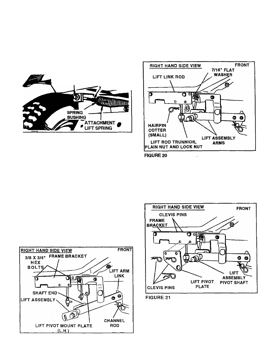
20. Assemble trunnions that were assembled'fo the
lift link rods in step 12, through lift-assembly arms
and secure with 7/16" flat washers and (small)
hairpin cotters. Note: Trunnions must be posi
tioned to outside of lift assembly arms. See
figure 20.
18. Assemble lift arm link over channel rod and insert
pivot shaft end (from R.H. side of tractor) into hole
in L.H. lift pivot plate. See fiQ'ure 19. Secure lift
arm link to channel rod with 1/8" (large) hairpin
cotter. See figure 19
19. Assemble the frame bracket (RH) under the right
hand foot rest of the tractor usinf two 3/8 x 3/4"
hex bolts. Tighten securely taking care not to
strip threads. See figure 19.
21. Assemble lift pivot plate over right hand end of lift
assembly pivot shaft and connect to outside of
frame bracket using two 3/8“ x 3/4" clevis pins
from inside. Secure with two 3/32“ (small) hairpin
cotters. Secure ends of pivot shaft to each lift
pivot plate with 1/8" (large) hairpin cotter. See
figures 20 and 21.
22. Assemble support bracket onto right hand side of
tractor using two 3/8" x 1" hex bolts inside and secure,
with, 3/8" lock washers, and 3/8" hex lock nuts on
outside. See figure 22.
FIGURE 19