Note – Sears 486.24412 User Manual
Page 7
Attention! The text in this document has been recognized automatically. To view the original document, you can use the "Original mode".
9 .
Re-assemble plactic caps on top ends of spring
adjustment bolts.
NOTE
SEE ADJUSTMENT SECTION ON
PAGE 10 FOR SPRING TENSION.
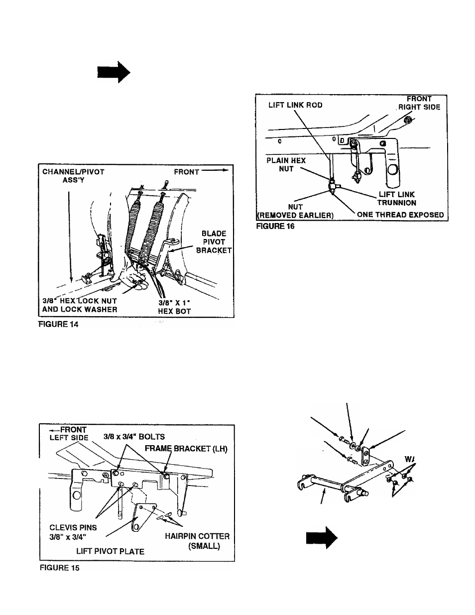
Assemble blade pivot bracket on to top right hand
side of channel/pivot assembly. See figure 14.
Assemble two 3^“ x 1" hex bolts down through
bracket and plate and secure with two 3/8" lock
washers and 3/8" hex nuts underneath.
10. Assemble the frame bracket (LH) under the left
hand foot rest of the tractor using two 3/8 x 3/4"
hex bolts. Tighten securely being careful not to
strip threads. See figure 15.
11. Assemble the lift pivot plate to th§T®ft hand frame
bracket using two 3/8" x 3/4" clevis pins and
secure wth two 3/32“ (small) hairpin cotters. See
figure 15.
12. Assemble 3/8" plain hex nut, lift rod trunnion and
lock nut (removed from tractor lift link rod in
tractor preparation section) onto right and left
hand lift link rods until one thread is below bottom
of nut. Tighten nuts lock trunnion in place. See
figure 16.
13. Pre-assemble lift arm link to inside of long arm on
lift assembty. As shown in figure 17.
14. Assemble one 3/8" x 1-1/4“ hex boll through 3/8"
flat washer, through pivot bushing, through large
hole in lift arm link near angle end and through
hole in long arm nearest the end. Secure with one
3/8" lock washer and one 3/8" hex lock nut. See
figure 17. NOTE; Lift arm link must pivot freely.
15. Assemble one 3/8" x 1“ hex bolt through second
hole form end of long arm. Secure with one 3/8“
lock washer and one 3/8“ hex lock nut. This boll
is used as a limit stop for the lift arm link. See
figure 17.
3/8" FLAT WASHER
3/8"
X M/4"
HEX BOLT
3ffi"x1"
HEX BOLT
LIFT
ASSEMBLY
PIVOT
BUSHING LIFT ARM
LINK
3/8" LOCK
VSHER
3/8" HEX
LOCK NUT
FIGURE 17
NOTE
Lift arm link must be positioned
as shown in figures 17 and 19.