Note, Assembly instructions – Sears 486.24412 User Manual
Page 4
Attention! The text in this document has been recognized automatically. To view the original document, you can use the "Original mode".
ASSEMBLY INSTRUCTIONS
TOOLS REQUIRED FOR ASSEMBLY
1)
7/16“ Open End or Box Wrench
0)
1/2“ Open End or Box Wrench
(1)
9/16“ Open End or Box Wrench
(1)
3/4“ Open End or Box Wrench
(1) Adjustable Wrench
(1) Hammer
Refer to carton contents figure on page 2 and
figure 1 on page 3 for parts and hardware needed
to assemble dozer blade.
NOTE
RIGHT HAND (R.H.) AND LEFT HAND
(L.H.)
ARE
DETERMINED
FROM
OPERATOR'S
POSITION
WHILE
SEATED ON TRACTOR.
1
.
Assemble curved end of angle lock spring intp
small hole in washer as shown in figure 2.
FIGURE 2
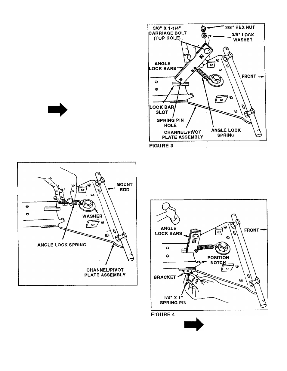
2. Assemble the two angle lock bars together as
shown in figure 3, using one 3/8" x 1 -1/4“ carriage
bolt down through the top holes with a 3/8“ lock
washer and a 3/8" hex nut underneath. Do not
tighten at this time.
3. Assemble the offset end of angle lock spring into
small holes in angle lock bars as shown in figure
3. Slide lock bars through lock bar slot until spring
pin hole is aligned with bracket on back side. See
figure 4. Using a hammerdrive 1/4“ x 1 “ spring pin
into lock bars until flush with bracket. See figure
4. Tighten nut in angle lock bars which was left
loose in step 2.
NOTE
Lock bars should pivot freely and when
pulled all the way back the channel/pivot
plate assembly should be unlocked and
free to pivot to right or left position notches.