To adjust height of cut (cont'd), Rear deflector, To assemble grass catcher – Sears 917.372301 User Manual
Page 7: How to set-up youe mowee, T'd)
Attention! The text in this document has been recognized automatically. To view the original document, you can use the "Original mode".
TO ADJUST HEIGHT OF CUT (CONT'D)
CAUTION: DO NOT change the height of cut with
the engine running.
1. The wheel adjusters give you five (5) different
cutting positions. Medium cut is the best for
most
fawns.
2. High cut is approximately 3
5/8",
medium cut
is approximately 2 I
/2",
and low cut is approx
imately I
3/8".
There are two (2) other posi
tions, Pick the position which suits you for best
cutting
fSee
Fig.
6)
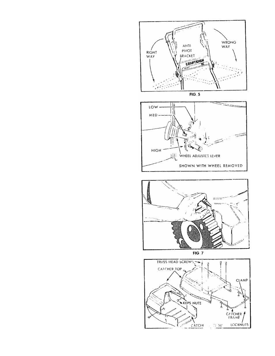
3.
The wheel adjusters on your lawn mower can
be easily adjusted as shown
in Fig.
7. To
change the height of cut, squeeze adjuster
lever toward the wheel, moving up or dow n
to selected height. Be sure all wheels are
in
the same setting
(See
Fig.
4r When cutting in heavy or
mniit
grass, the
rear
of the lawn mower may be raised one
setting
higher to allow better discharge of the grass.
REAR DEFLECTOR
The rear deflector, attached
between
the rear
wheels of your lawn mower, was assembled at
the factory and requires
no assembly.
TO ASSEMBLE GRASS CATCHER
NOTE: The grass catcher for your mower is sup
plied unassembled. To assemble your grass cat
cher follow steps below,
h Position clamp onto catcher frame as
shown in
(Fig, 8) and
close ends of clamp,
2. Put grass catcher frame info catcher top (See
Fig. 8).
3.
Put one (1) ttlO-24 x 5/8 truss head screw info
hole in catcher top and clamp and HI0-24 lock
nuts. DO NOT TIGHTEN (See Fig. 8).
4. Put
three
(3)
HI0-24 x 5/8
truss head screws
info the
coicfier frante
using HI0-24 locknuts.
Use a flat blade screwdriver to drive screws
while holding the locknuts with adjustable or
3/8"
wrench (See Fig. 8).
5.
Position
baffle inside of catcher top as
shown
in (Fig. 9).
Put two (2) HIO-24 truss head screws
into holes with two (2) HIO-24 locknuts. Use a
flat blade screwdriver to drive screws while
holding the locknuts with adjustable or 3/8"
wrench.
6. Position top half of catcher on the bottom half
(See Fig. 8).
7. Align the holes
in
sides of top and bottom
halves of catcher,
8. Install the eight (8) 1/4-20 x 5/8"
fruss
head
screws with the eight (8) 1/4-20 "Keps" nuts
into the holes in the catcher side.
9. Tighten the
screws
with
a
flat blade screw
driver.
10. Hold the "Keps" nuts with an adjustable or
7/16" wrench while tightening the screws.
NOTE: Be sure all screws and nuts are tight.
HOW TO SET-UP YOUE MOWEE
(
con
T'D)
FIG 6
FIG