Blade/blade flange care (cont'd), Rear deflector, To adjust drive control cable – Sears 917.372301 User Manual
Page 12: Gear case, Maintenance
Attention! The text in this document has been recognized automatically. To view the original document, you can use the "Original mode".
BLADE/BLADE FLANGE CARE (CONT'D)
NOTE: The blade flange with fab attaches the
blade to crankshaft. It is not intended to protect
the crankshaft. The tab must be in good condition
and located in slot of crankshaft to keep blade
attached.
5. Put the blade flange on the engine crankshaft
with the tab in the slot of the crankshaft (See
Fig. 19).
6. Put the blade on the crankshaft as
shown
in
(Fig. 19). Be sure the word "TOP" (stamped
in the blade) is toward the engine.
7. Install the flat washer, two (2) formed washers
and blade nut as removed above.
NOTE:
We recommend
that the blade nut be re
placed when installing a
new
blade.
8. Tighten blade nut. The recommended tighten
ing torque is 50-65 ft. lbs. Use block of wood
to prevent blade rotation.
NOTE: Torque wrenches are available at most
Sears retail stores and through the catalog.
A loose blade can result in difficult starting of
engine.
We do not recommend sharpening blade-but if
you do, be sure blade is balanced. An unbalanced
blade can cause excessive vibration and contri
bute to shortening the life of the engine and
mower.
REAR DEFLECTOR
The rear deflector which is attached to the rear of
your mower is to keep objects from being thrown
out the back of the mower. If your rear deflector
becomes damaged you should replace if (See
Fig. 20).
TO ADJUST DRIVE CONTROL CABLE
NOTE: THE DRIVE CONTROL CABLE SHOULD BE
CHECKED OFTEN TO BE SURE THAT GEAR CASE
SHIFTER IS FULLY ENGAGED OR WHENEVER
SERVICE HAS BEEN PERFORMED ON THE GEAR
CASE OR DRIVE CONTROL COMPONENTS.
1. To adjust, remove the drive cover by removing
two (2) screws. Keep for re-use (See Fig. 16).
2.
Loosen screw
holding cable clamp (See Fig.
17).
3.
Loosen screws
holding cable clamp "A"
&
"B"
(See Figs. 17 and 21).
4. Loosen both jam nuts "C" & "D" at the cable
clamp on the gear case adjusting brocket
(See Fig. 17).
5. Unhook clutch spring from shifter arm
(See
Fig. 17).
6. Hold, clip or tape down the drive control bar
and engage the drive control (See Fig. 13).
7. Move the shifter arm to drive position. To be
sure the jaw clutch is fully engaged, rotate the
front wheels.
MAINTENANCE
(C
ont
'D)
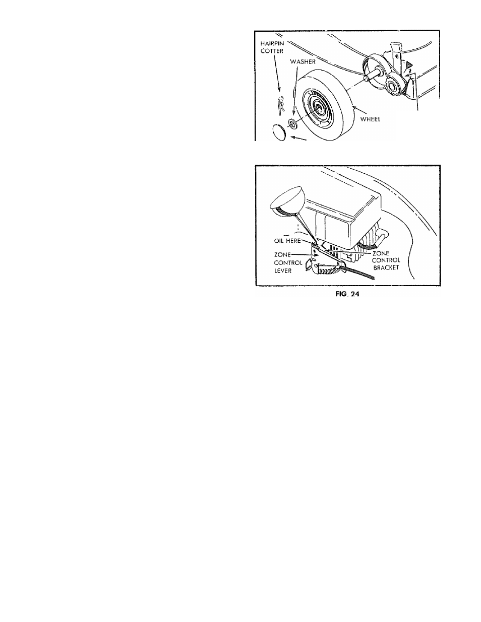
OIL HERE
EACH SIDE
HUBCAP
FIG. 23
12
8. Hold shifter arm in fully engaged position by
pliers as shown in Fig. 17. DO NOT pull on
control cable.
9. Tighten jam nut "C" up to bracket until cable is
snug.
10. Tighten cable clamp
screw "B" (See Figs. 17
and 21).
11.
Tighten jam nut "D" up to bracket
(See
Fig. 17).
12. Tighten screw "A".
13. Put clutch spring back in place on shifter arm,
removed
in step 5
above.
14. With drive control in engaged position, push
mower
back and forth to be sure gear case is
fully engaged.
NOTE: Be
sure to disengage drive
control before
starting engine.
15. Put drive cover back in place, removed in step
1
above.
GEAR CASE
1. THE GEAR CASE AND AREA AROUND ALL THE
DRIVE SHOULD BE KEPT CLEAN AND FREE OF
TRASH BUILD-UP.
2. To check gear case area:
a. Remove the drive cover by removing the
two (2)
screws (See
Fig. 16). Keep for re
use.
b. Clean trash from around gear
case.
c.
Put drive
cover
back, removed in (a)
above.