Vermont Casting 820 User Manual
Page 31
31
Vermont Castings Jefferson Direct Vent/Natural Vent Gas Heater
20002191
Gasket Replacement
The Jefferson Gas Heater uses a ‘tadpole’ type gasket
to seal between the glass panel and the frame. In time,
this gasket can become brittle and compressed and
should be replaced. New gasket is available from your
dealer.
Shut off the gas supply and allow the stove to cool.
Wear safety goggles and a dust mask.
1. Remove the Front, Glass Frame and Glass Panel.
(Figs. 59 & 60) Remove the old gasket. Use a razor
blade to separate the glass and gasket from the
frame, and to clean the glass of any remaining
cement or bits of gasket. Use a cold chisel if neces-
sary.
2. Determine the correct length of gasket by laying it
out around the edge of the glass. Allow an extra 1 -
2” (25-50mm). Mark the spot to be cut. Use a utility
knife.
3. Starting on a long edge, remove about 6” of the
protective paper strip and apply the flat adhesive
face of the gasket around the outside-facing edge of
the panel. Continue around the panel, applying a
bout 6” at a time and being careful to not stretch the
material. Do not overlap the gasket ends. (Fig. 61)
4. Apply a thin bead of high temperature silicone
rubber sealant along the inside corner of the glass
frame, all around the perimeter. Place the flat
gasketed side of the glass panel back into the steel
frame. Pinch the rounded inside-facing gasket
material to bulk it up.
5. Replace the glass frame and front panel as previ-
ously described.
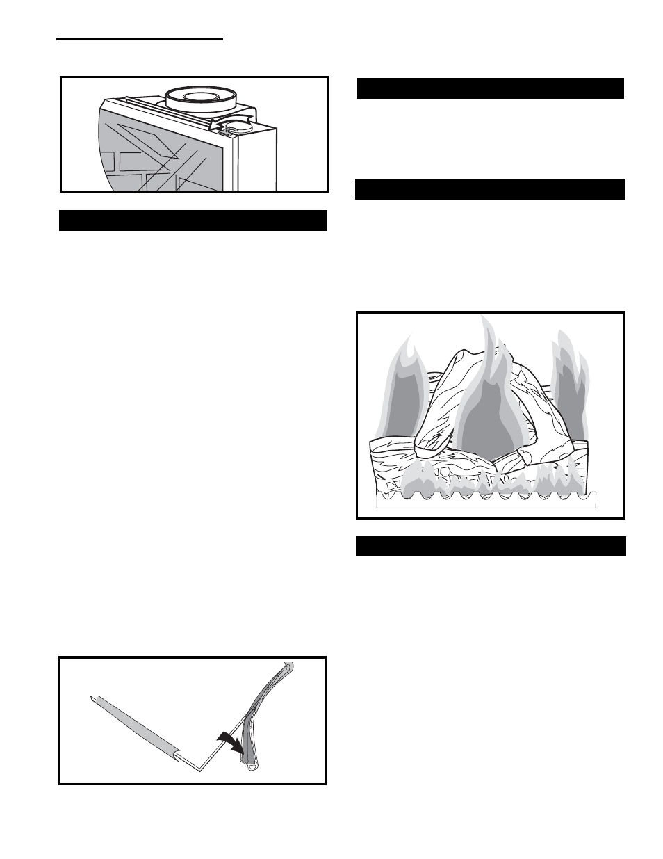
Check the Gas Flame Regularly
To ensure that the stove is operating properly, check
the flames periodically to confirm that they match
Figure 62. The flames will be blue during the first 15-20
minutes of operation, and will gradually turn to yellow
after that.
Do not use your stove if the flame pattern differs from
that shown here. Contact your Vermont Castings dealer
or a qualified technician for help.
Inspect the Vent System Annually
Have the vent system inspected annually by a qualified
technician. Shut off the main gas supply before inspect-
ing the system. Both the inner exhaust pipe and the
outer combustion supply pipe must be checked to
confirm that they are unblocked and in good condition.
Stove Disassembly
If there is ever a need to remove the firebox assembly
from the stove shell, support the firebox with solid
stands about 6” (150mm) tall under the left and right
outer edges of the firebox base. Do not set the firebox
assembly directly on the floor; this can damage the
control valve and/or the gas lines from the valve to the
firebox.
Before removing the firebox from the shell, disconnect
the on/off switch wires from the valve. If the assembly
includes the optional fan, disconnect the fan rheostat. If
the installation includes a wall thermostat, disconnect
the thermostat leads from valve.
Disconnection and reconnection to the gas line should
only be done by a qualified gas service technician.
Upon reinstallation, the vent system must be sealed to
the firebox as shown in the installation section, Page
14. Also be sure the logs are placed in the firebox
correctly, as shown on Page 20.
ST179
Fig. 61 Wrap the gasket material around the outside edge of
the glass.
ST234
Fig. 62 Correct flame pattern.
ST208a
Fig. 60 Release the latches to release the glass frame.