Table 2. injector orifice size matrix – Vermont Casting 820 User Manual
Page 29
29
Vermont Castings Jefferson Direct Vent/Natural Vent Gas Heater
20002191
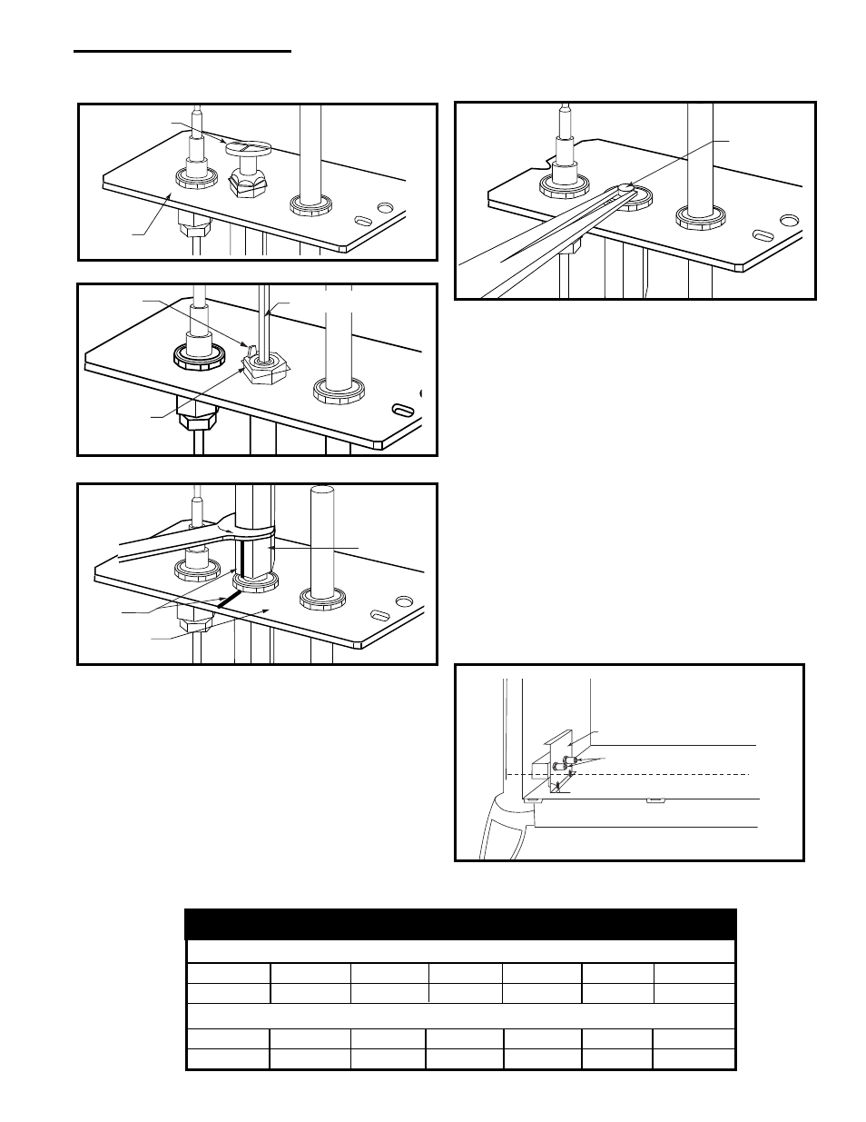
16.Replace burner. Slide the burner in at an angle with
left side lower than the right side. Slide the left side
onto the injectors, making sure the burner leg remains
at a 90
°
angle to the base. Lower the right hand side
down in to place. Make sure the burner is as far left as
possible and the injector shoulders are inside the
burner.
NOTE: It is very critical to keep the left burner leg, which
holds the injectors, at a 90
°
angle to the base. (Fig.
58) This keeps the orifices aligned with the tubes
inside burner. Failure to do so could affect the flame
appearance and performance of the unit.
19.Place conversion label on valve.
20.Reinstall the right and left log bracket assembly.
21.Reinstall the rear log bracket.
22.Replace logs.
23.Replace glass and stove front.
Conversion is complete.
90
°
Left Burner Leg
Injector Orifices
ST353a
Fig. 58 Remove and replace injector orifices.
Table 2. Injector Orifice Size Matrix
Conversion to Natural Gas
Input (BTU/h)
Kit #
Front
Part #
Rear
Part #
Minimum
Maxi,mum
000-5021 #54 / .055” 20000130 #44 / .086” 30000334
19,000
28,000
Conversion to LP
Input (BTU/h)
Kit #
Front
Part #
Rear
Part #
Minimum
Maximum
000-5022 #69 / .029” 30000513 #54 / .055” 20000130
20,000
28,000
Pilot Hood
Pilot
Bracket
CO105a
Fig. 54 Remove pilot hood.
Index Tab
Snap Ring
Allen Wrench
CO106a
Fig. 55 Remove pilot orifice.
•
Remove pilot orifice with needlenose pliers. (Fig. 57)
NOTE: Use a wrench to hold pilot tube in place while
removing the orifice.
•
Install the conversion orifice.
•
Reinstall pilot hood and tighten until mark on pilot
hood aligns with mark on pilot bracket.
14.Remove injector orifices from left burner leg using 1/
2” wrench. (Fig. 58)
15.Install conversion orifices. (Refer to Table 2)
NOTE: Be sure burner leg remains at a 90
°
angle to
firebox base after conversion.
Pilot Hood
Index
Marks
Pilot Bracket
CO105
Fig. 56 Remove pilot hood.
Pilot
Orifice
CO106b
Fig. 57 Remove pilot orifice.