Sears BODYLEFT 831.159412 User Manual
Page 8
Attention! The text in this document has been recognized automatically. To view the original document, you can use the "Original mode".
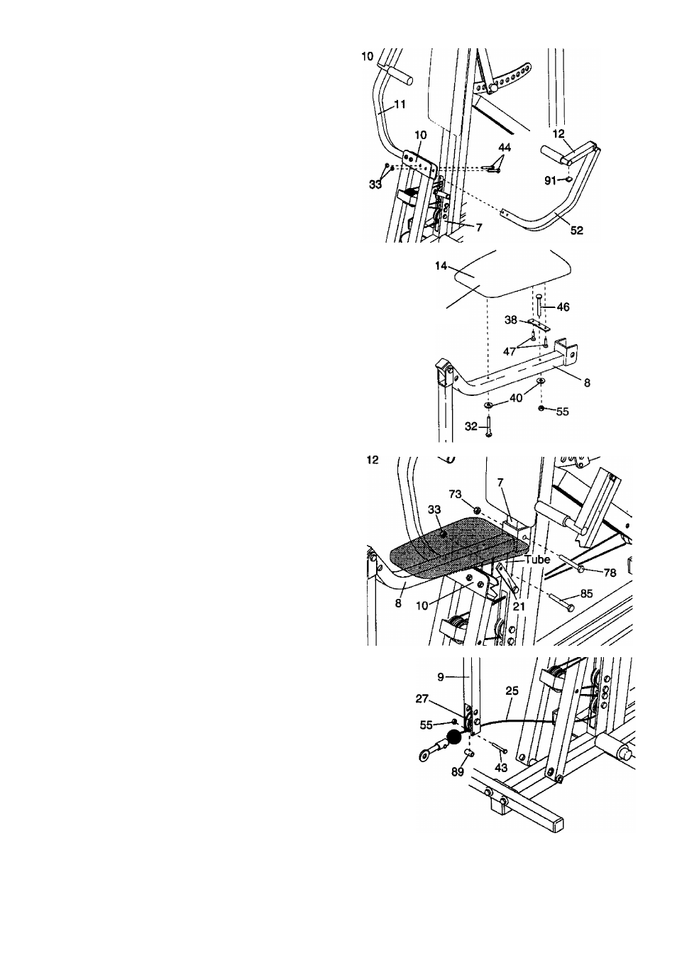
10. Pull the Moment Arm (10) fonward. Hold the lower
end of the Left Press Arm (52) in ttie upper end of
the Moment Arm. The Left Press Arm must be
turned so the Handle (12) Is on the side shown.
Attach the Left Press Arm with two 3/8" x 2 1/2”
Bolts (44) and two 3/8” Nylon Locknuts (33).
The
Bolts must be Inserted from the side shown, or
the BODYLIFT will not function properly.
Press a Small Bumper (91) onto the underside of
the Handle (12).
Assemble the Right Press Arm (11) in the same
manner.
11. Insert the 1/4" x 21/2” Carriage Bolt (46) into the
Seat Bracket (38). Attach the Seat Bracket to the
Seat (14) with the two 1/4 x 3/4” Screws (47).
Insert the 1/4" x 2 1/2" Carriage Boit (46) into the
indicated hole in the Seat Frame (8). The narrow
end of the Seat must be facing the curved end of
the Seat Frame. Tighten a 1/4” Nylon Jam Nut (55)
with a 1/4” Flat Washer (40) onto the Carriage Bolt.
Attach the other end of the Seat to the Seat Frame
with a 1/4” x 2 1/2” Screw (32) and a 1/4" Flat
Washer (40).
12. Attach the Seat Frame (8) to the Front Upright (7)
with the 5/16" X 2 3/4” Boit (78) and a 5/16" Nylon
Locknut (73). The Moment Arm (10) must be in
front of the indicated tube on the Seat Frame.
Attach the Seat Braces (21) to the Seat Frame (8)
with a 3/8” X 2 3/4” Bolt (85) and a 3/8" Nylon
Locknut (33). Tighten the Nylon Locknuts on both
ends of the Seat Braces.
13. Hold the Cable (25) under the indicated 31/2”
Pulley (27). Hold the 1/2" x 1” Sleeve (89) between
the small holes in the lower end of the Leg Lever
(9). Attach the Sleeve with the 1/4” x 1 3/4" Bolt
(43) and a 1/4” Nylon Jam Nut (55). The Cable
must be between the Pulley and the Sleeve.
11
Narrow End
13
8