Fig. 4 — field wiring connection details – Carrier 50BA User Manual
Page 5
Attention! The text in this document has been recognized automatically. To view the original document, you can use the "Original mode".
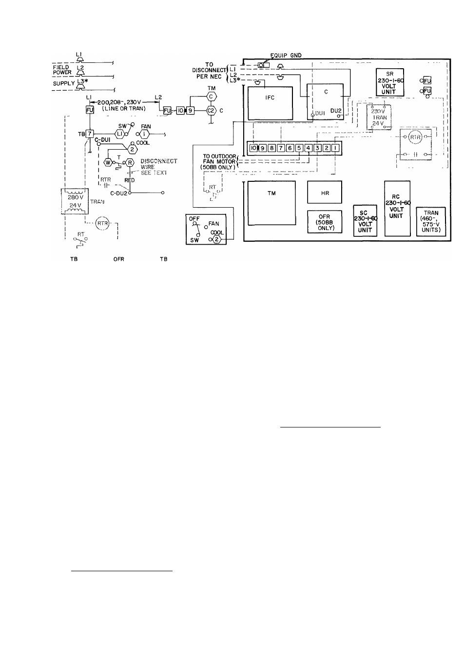
SCHEMATIC
COMPONENT ARRANGEMENT
[
4
]—BLU—(Т)-11-(з)—BLU-(5]--
TO OUTDOOR
FAN MOTOR
(50BB ONLY)
«
C
— Compressor Contactor
DU
— Dummy Terminal
Fu
— Fuse
Gnd — Ground
HR
— Holding Relay
OFR
— Outdoor Fan Motor Relay
RC
— Run Capacitor
RT
— Remote Thermostat
RTR
- R emote Thermostat Relay
SC
— Start Capacitor
SR
— Start Relay
Sw
— Switch
*L
3
applies to 3-phase units only
T
—Thermostat (factory-installed)
TB
— Terminal Board
TM
-T ¡met Motor
TRAN
— T ransformer
□
о
о
Terminal Block Terminal
Terminal (unmarked)
Terminal (marked)
. Factory Wiring
. Field Wiring
NOTES:
1
Shaded components and wires indicate field-installed remote
thermostat as described in instructions.
2
Refer to unit label diagram for complete wiring.
3
Field-supplied
transformer
(Carrier
Part
No.
HT01AA140)
and
remote
thermostat
reiay
(Carrier
Part
No.
HN61KJ007)
may be fieid installed in unit main control box as shown.
4
Field-supplied
remote
thermostat
(24-volt)
may
also
include
heating controls as desired.
Fig. 4 — Field Wiring Connection Details
START-UP
OFF. Set thermostat at
#
1. Set selector switch at
highest setting.
2.
Turn on unit power. Check that crankcase
heater (50BB units only) is on. Compressor
shell in vicinity of heater should become warm
to the touch. See Service, Crankcase Heater.
3. On 50BA units turn on condenser water supply.
On 50BB units open refrigerant line service
valves.
4. Set selector switch at FAN position. Check fan
speed and rotation direction. See Service sec
tion regarding fan adjustment procedures. Fan
direction arrow is affixed to fan scroll.
5.
50BA units (water-cooled) — Set selector
switch at COOL. Turn thermostat switch fully
counterclockwise.
Compressor will start within 5 minutes as
described in Service, Time Guard® Circuit.
5QBB units (condenserless) — After crankcase
heater has been energized (unit power on) for
at least 6 or 8 hours, set selector switch at
COOL. Turn thermostat switch fully counter
clockwise. Compressor will start within 5
minutes.
6.
Turn thermostat fully clockwise to shut off
compressor.
7. Then turn thermostat fully counterclockwise.
Compressor will start in about 5 minutes as
described in Time Guard Circuit. On remote
condenser unit 50BB outdoor air fans are
cycled with compressors.
8. Set thermostat for comfort as desired.
Shutting Down Unit — Set selector switch at OFF.
Do not shut off main power except to service unit.
Crankcase heater (50BB units) is operative only
when unit power is on. See Service, Crankcase
Heater discussed later.