Fig. 1 — base unit dimensions – Carrier 50BA User Manual
Page 2
Attention! The text in this document has been recognized automatically. To view the original document, you can use the "Original mode".
LEFT SIDE VIEW
FRONT VIEW
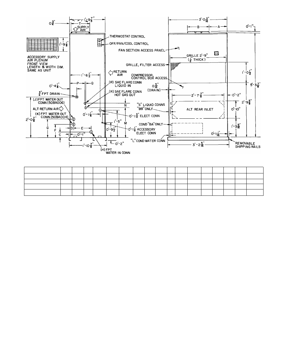
DIMENSIONS (ft-in.)
UNIT A
B
c
D
F
F
G
H
J
K
L
M
N
P
Q
R
s
T
50BA004Ì 1-1OV
2
1-1
0-3%
0-2
0-1 OVa
0-8
_
O-OV
2
0-0V2
0-y«
_
_
_
—
_
_
l-UXe
50BB004 Ì 1- OV,
1-1
o-ey«
o-oy«
0-0V2
0-r/a
l-l“/i6
50BA006Ì 0-1 Oy«
1-3
0-3 V
b
0-2
0-1 OV
b
_
0-1 1 V
b
0-0%4
o-oy4
_
0-V2
_
_
—
—
-
1 -4yi6
50BB006] b-lOVs
1-3
-
-
-
-
-
-
-
-
l-6^/26
0-2^/l6
O-S'/a
o-oy«
0-0V2
0-1 V
b
l-4yie
Certified dimension drawings available on request.
NOTE
Minimum required clearance at back and right side of unit is zero
Clearance above and at left of unit depends on space required for
accessory
plenum,
ductwork,
condenser
piping,
accessory
heater
piping, condensate drain line and power wiring Clearance required
at front of unit for service access and free return airflow is 2 feet
Fig. 1 — Base Unit Dimensions
2. Attach 1-in. flange to unit back panel or attach
a flanged, flexible duct connection directly to
unit as desired. If an outdoor makeup air
damper is to be installed, attach directly to unit
back panel and install flexible connection
between damper assembly and remaining duct
work. Use accepted ductwork installation
procedures. Follow all applicable codes.
3. Restrict or completely blank off the standard
return air opening with a field-fabricated filler
panel using dimensions shown in Fig. 1. This
panel must be removable for service access.
Refer to Service, Return Air Grille Removal as
required.
Water-Cooled Condenser Connections (50BA
Units) — Connect condenser water supply and
return lines to connections shown in Fig. 1. To
prevent condenser inlet and outlet stubs from
twisting when connecting water lines, hold them
firmly with a wrench at the FPT hex fitting. Do
not use water lines smaller than connection sizes
all applicable plumbing and
shown. Observe
sanitary codes.
Install a water regulating valve in water supply
line outside unit cabinet as follows:
1. Route water regulating valve capillary and flare
nut to fitting on refrigerant liquid line (Fig. 2)
using any convenient unused opening on side of
unit. Use a grommet in unit panel to prevent
chafing of capillary line.
Remove cap from liquid line fitting.
Insert the cotter pin (taped to liquid line near
fitting) split end first into water regulating valve
flare nut.
Connect flare nut to fitting. Round end of
cotter pin will depress fitting core, thus opening
fitting to allow refrigerant pressure to act on
water regulating valve. Tighten flare nut to
prevent leakage.
The fitting will automatically seal (close) when
flare nut is loosened and removed; however, a
slight amount of refrigerant is lost each time.
Do not lose cotter pin.
(Continued on P. 4)
2
.
3.
4.
5.
i