Installation step 4 – Chamberlain 2000SDC 1/2HP User Manual
Page 13
Attention! The text in this document has been recognized automatically. To view the original document, you can use the "Original mode".
Installation Step 4
Install the Safety Reversing Sensor
(Receiving and Sending Eyes)
Figure 1
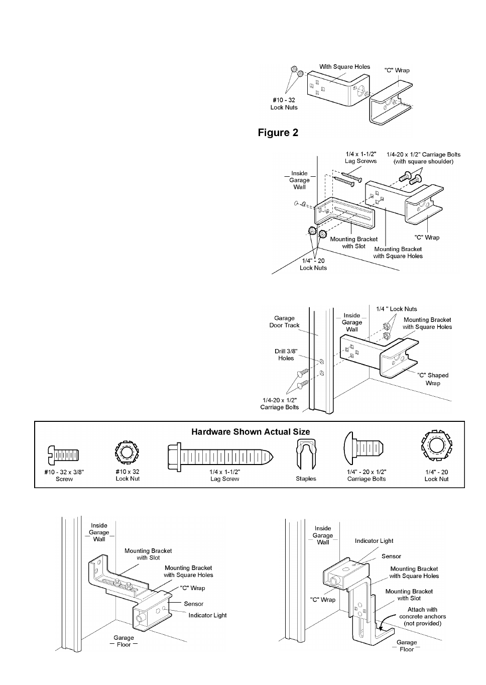
Figures 1, 2 and 3 show recommended assembly of
bracket(s) and "C" wrap based on the wall installation of
the sensors on each side of the garage door as shown on
page 12, or on the garage door tracks themselves.
Figures 4 and 5 are variations which may fit your
installation requirements better. Make sure the wraps
and brackets are aligned so the sensors will face each
other across the garage door.
Garage Wall or Door Track Installation Procedure
• Fasten the "C" wraps to the mounting brackets having
square holes, using the hardware shown in 1.
Garage Wall Installation Procedure
• Connect each assembly to a slotted bracket, using the
hardware shown in 2. Note alignment of brackets for
left and right sides of the door.
• Finger tighten the lock nuts.
• Use bracket mounting holes as a template to locate and
drill (2) 3/16" diameter pilot holes on both sides of the
garage door, 4"-6" above the floor but not exceeding 6"
(see warning on page 12).
• Attach bracket assemblies with 1/4"x1-1/2" lag screws
as shown in 2.
• Adjust right and left side bracket assemblies to the same
distance out from mounting surface. Make sure all door
hardware obstructions are cleared. Tighten the nuts
securely.
Garage Door Track Installation Procedure
Discard slotted bracket. Drill 3/8" holes in each track and
fasten securely with hardware as shown in 3.
Garage WALL or DOOR TRACK Installation
Mounting Bracket
#10-32x3/8"
Screws
Garage WALL Installation
Figure 3
Garage DOOR Track Installation
Figure 4
Alternate Wall Mount
Figure 5
Alternate Floor Mount
13