Service, Lubrication, To add or remove compressor oil – Carrier 38JB User Manual
Page 6
Attention! The text in this document has been recognized automatically. To view the original document, you can use the "Original mode".
Every full turn counterclockwise decreases load
point by 7.5 psig.
PRESSURE
DIFFERENTIAL
(difference
be
tween cylinder load and unload points) is adjust
able from 6 to 22 psig. To adjust, turn pressure
differential adjustment counterclockwise to its back
stop position. In this position, differential is 6 psig.
Turn adjustment clockwise to desired pressure
differential. Every full turn clockwise increases
differential by 1.5 psig.
SERVICE
Turn off main power before servicing unit.
Condenser Coil
— Remove dirt and debris from
coil as required. Clean with a stiff brush, vacuum
cleaner or compressed air.
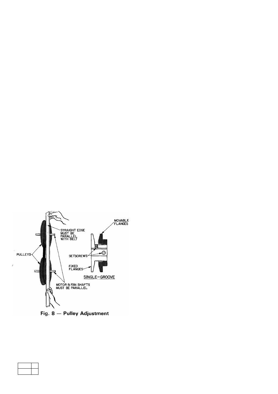
Condenser Air Fan Adjustment
— Speed (see
Table 1) and alignment is factory set, adjust as
follows;
TO CHANGE FAN SPEED:
1. Loosen fan belt by loosening fan motor mount-
ing plate bolts.
2. Loosen pulley movable flange setscrews (Fig. 8).
3. Screw movable flange toward fixed flange to
increase speed and away from fixed flange to
decrease speed.
Increasing fan speed increases load on motor. Do
not exceed maximum fan speeds (Table 1).
4. Tighten movable flange setscrews at nearest flat
surface of pulley hub.
TO ALIGN FAN AND MOTOR PULLEYS —
Loosen fan pulley setscrews and slide fan pulley
along fan shaft. Make angular alignment by loosen
ing motor from mounting plate. Check alignment
with a straight edge (Fig. 8).
TO ADJUST BELT TENSION — Loosen motor
mounting plate bolts. Slide motor mounting plate
as required to attain approximately 3/4-in. belt
deflection with one finger.
Lubrication
FAN MOTORS have sealed lubricated bearings.
No provisions for lubrication are made.
FAN SHAFT BEARINGS have been factory
greased. After first 6 months of unit operation,
regrease twice a year, preferably prior to each heat
ing and cooling season. Add grease slowly with shaft
revolving until grease rapidly oozes from pressure
relief hole in grease fitting.
COMPRESSOR has its own oil supply. Loss of oil
due to a leak in the system should be the only
reason for adding oil after the system has been in
operation. Sight glass should be 1/2 full of oil.
To Add or Remove Compressor Oil
1. Pump down compressor to 2 psig and close
suction and discharge service valves. Vent re
maining pressure in compressor to atmosphere.
2. Add oil thru oil filler connection.
3. To remove oil, remove compressor crankcase oil
drain plug.
Refer to Standard Service Techniques Manual,
Chapter 1, or 06D Compressor Service Instructions
for complete instructions on checking, adding or
removing compressor oil.
Refrigerant Charge
— The approximate unit
charge is listed in Table 1. Refer to Carrier Stand
ard Service Techniques Manual, Chapter 1,
Refrigerants.
A clear sight glass does not always indicate ade
quate refrigerant charge. If a low charge is sus
pected, purge until sight glass flashes. Block
condenser coil air inlets to maintain 300 ± 5 psig
discharge pressure. Charge slowly until sight glass
clears, then add an additional charge as specified
in the instructions for the evaporator unit.
If low-pressure switch is jumpered for charging,
remove jumper.
For replacement items use Carrier Specified Parts.
Manufacturer reserves the right to discontinue, or change at any time, specifications or designs without notice and without incurring obligations.
Book 1
Tab
3a
Form 38JB-3SI Supersedes 38JB-1 SI
Printed in U S A
9-80
PC111
Catalog No 533-889