Step 4 — provide for unit condensate disposal – Carrier 38JB User Manual
Page 3
Attention! The text in this document has been recognized automatically. To view the original document, you can use the "Original mode".
&■
“T^
CONDENSER COIL
f
t
?
-----
g-------
Contact local power company for correction of
improper line voltage.
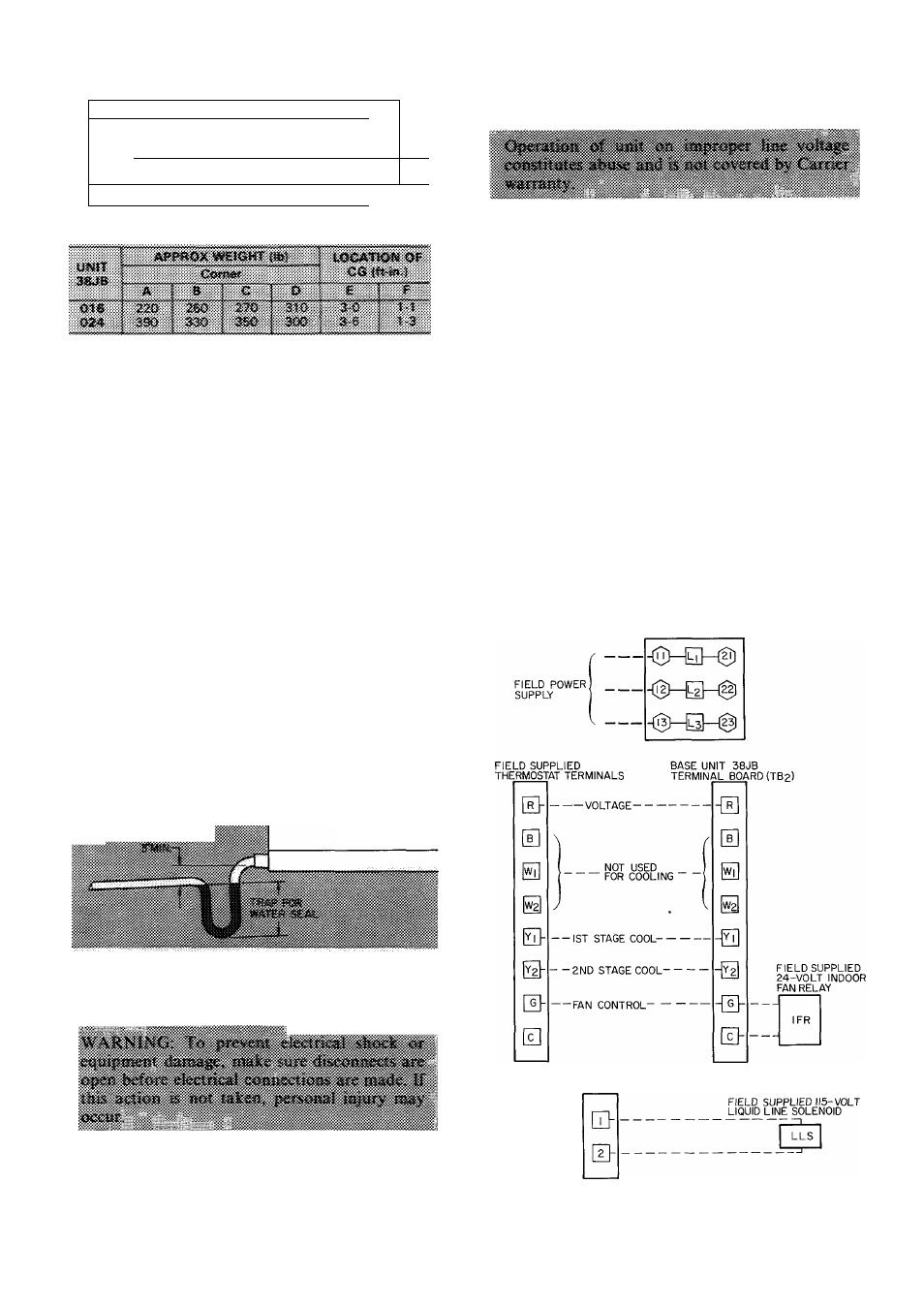
Fig. 2 — Weight Distribution
vapor barrier. If ducts are not insulated, install
dampers in wall openings to prevent cold air from
entering ducts and unit. Insulate inside of duct
within 12 in. (minimum) of unit. Also insulate
bottom of unit (basepan) to prevent condensation
from forming on unit if unit is installed off the floor.
Install louvers in wall openings to prevent rain
from entering ducts and unit. Arrange louvers or
other air deflection baffles to prevent recirculation
of outdoor airflow thru condenser.
If condenser air inlet filters are not used, provide
an access door in condenser air inlet duct for
coil cleaning.
Step 4 — Provide for Unit Condensate
Disposal
BASEPAN DRAIN — Trap 1/2-in. diameter drain
in unit basepan for proper condensate disposal, see
Fig. 3. Refer to Carrier System Design Manual,
Part 3 for additional trap design details.
'„'g
38JB
UNIT
Fig. 3 — Trap for Drain
Step 5 — Make Electrical Connections
Field wiring must comply with local and national
fire, safety and electrical codes. Voltage to unit
must be within 2% of voltage and 10% of current as
indicated on nameplate. See Table 2.
BRING LINE POWER LEADS INTO UNIT —
Install airtight conduit connectors in side panel
knockouts. Route all wires thru connectors to
terminal blocks in control box. Refer to Fig. 4 and
unit label diagram. Use copper, copper-clad alumi
num, or aluminum wire from power supply. If
aluminum wire is used, coat wire ends with a corro
sive inhibiting flux. Install unit ground.
CONNECT CONTROL POWER WIRING — See
Fig. 4. Make field power wire connections to
terminal board (TBl).
Connect field-supplied thermostat to terminal
board (TB2). Terminals C and G are provided for
field-supplied
indoor
fan
relay
connections.
Operate thermostat and indoor fan relay on 24 volts.
The 38JB016 has a third terminal board (TB3)for*
115-volt liquid line solenoid valve connections. Use
7/8-in. diameter knockout. See Fig. 1 for wiring^
liquid line solenoid valve into control box.
BASE UNIT 38JB
TERMINAL BOARD (TB|)
BASE UNIT 38JB0I6 ONLY
TERMINAL BOARD (TB
3
)
Fig. 4 — Electrical Connections