Start-up – Carrier 38JB User Manual
Page 5
Attention! The text in this document has been recognized automatically. To view the original document, you can use the "Original mode".
l^íd Wnèbf $
Ompws&ún'
For piping instructions, refer to the Carrier
System Design Manual. Refer to Refrigerant
Charge and Carrier’s Standard Service Techniques,
Chapter 1, Refrigerants, when charging unit.
START-UP
Make sure unit has been installed in aeeordance
with installation instructions and all applicable
eodes. Check the following items before starting
unit.
Compressor Mounting
— Loosen eompressor
hold-down bolts until sidewise movement of flanged
washers under bolt heads is possible. Do not loosen
completely. Bolts are self-locking and retain
adjustment.
Internal Wiring
— Check all electrical connections
in unit control box, compressor terminal boxes and
other electrical components. Tighten as required.
Refrigerant Shutoff Valves
— Open (backseat)
compressor service valves fully. Replace and tighten
valve caps to prevent leaks. Open liquid line valve
in a similar manner.
Crankcase Heater
— Energize heater 24 hours
prior to start-up to prevent loss of oil in compressor.
Area near heater element should be warm to the
toueh.
Heater is automatically energized when com
pressor is stopped and de-energized when com
pressor is operating.
Compressor Oil Sight Glass
should be 1/2 full
of oil. See Service; Lubrication.
Air Fans and Motor
— Check belt and pulley
alignment. Refer to Condenser Air Fan Adjustment
as required.
Cooling
— To start unit, turn on main power
supply. See Crankcase Heater above. Set thermostat
to COOL, AUTO, and desired temperature. Wait
approximately 5 minutes for compressor to start.
See Time Guard® Circuit. Check cooling effect
at air supply grilles, fan speeds, refrigerant sight-
glass eonditions and operation of all controls and
safety devices.
Accessory Head Pressure Control
— A head
pressure-actuated piston operator, connected to a
damper, regulates airflow thru the eondenser. At
170 F psig diseharge pressure, damper starts to
open. Damper is fully open (horizontal position) at
250 psig.
Pressure Switches
(high and low) cut out at
settings shown in Table 1.
Time Guard® Circuit
provides a delay before
starting compressor after shutdown. At start-up,
timer delays compressor for 12 seconds after ther
mostat closes. On compressor shutdown, timer
recycles for 5-1/2 minutes. During this period,
compressor cannot restart. On 38JB024, timers are
set for a 12-second delay between start-up of
compressor no. 1 and compressor no. 2.
Winter Start
— Timer overrides low-pressure
switch for 2-1/2 minutes. During start-up at low
ambient conditions, this permits system suction
pressure to reach normal operating level. On a sus
tained low-pressure condition, the timer circuit
shuts down until low-pressure switch resets.
Capacity Control
— Two-step thermostat assem
bly cycles each of 2 compressors on 38JB024. On
38JB016, first stage of thermostat cycles com
pressor; second stage of the thermostat can be used
to operate a field-supplied liquid line solenoid for
2-stage operation. Compressor capacity control
unloader responds to suction pressure changes.
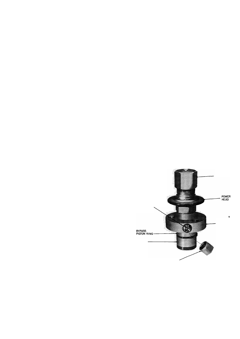
C
Compressor Capacity Control Unloader
(Fig. 7)
is suction-pressure actuated and controls 2 cylin
ders. Unloader is faetory set to unload at 60 psig
and load at 75 psig but may be field adjusted as
follows;
CONTROL
SET POINT
ADJUSTMENT
NUT
PRESSURE
DIFFERENTIAL
ADJUSTMENT
SCREW
VALVE BODY
BYPASS
PISTON
DIFFERENTIAL SCREW'
SEALING CAP
(CAP MUST BE REPLACED
TO PREVENT REFRIGERANT LEAKAGE)
Fig. 7 — Compressor Capacity Control
Unloader
CONTROL SET POINT (cylinder load point) is
adjustable from 0 to 85 psig. To adjust, turn control
set point adjustment clockwise to its bottom stop.
In this position, load point is 85 psig. Turn adjust
ment counterclockwise to desired load point.