Troubleshooting procedure, Troubleshooting sequence chart – Carrier 31MC User Manual
Page 9
Attention! The text in this document has been recognized automatically. To view the original document, you can use the "Original mode".
. TROUBLESHOOTING PROCEDURE
The following troubleshooting procedure has
been designed to speed the serviceman’s work and
f ,
ensure that any malfunction in the electronic air
"
cleaner is quickly detected and properly repaired.
1 Blower on,
Energize EAC
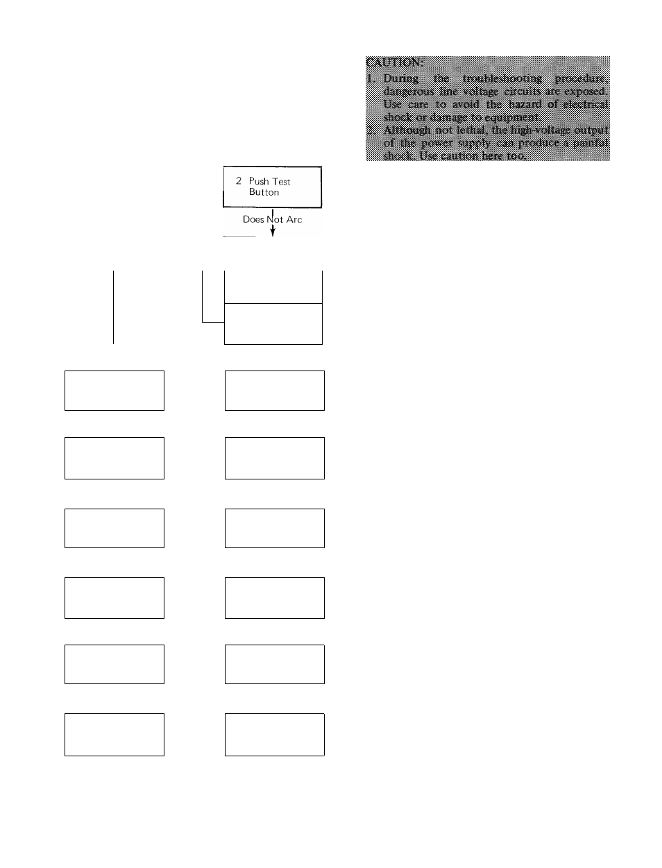
Troubleshooting Sequence Chart
—Light Orp»>-
Unit
Arcs
Check Surge
Resistor
Test Button
Ligh
Off
EAC Operating
Properly
3 Push Test
Button
Unit
Arcs
Check Light
Circuit
I
Does Not Arc
t
4 Remove Cells,
Replace Door
Light
On
Check Ceils,
Contact Tray.
Surge Resistor
Light Off
t
5 Push
Test Button
___,Unit ^
Arcs
Check Light,
Light Circuit and
Cells
1
Does Not Arc
t
6. Check Line
Voltage
Incorrect
Voltage
Check Voltage
Source and
Wiring
Line Voltage Correct
t
7 Disconnect Surge
Resistor, Energize
Power Supply
— Light On-^
Replace
Surge Resistor
1
Light Off
t
8 Check Output of
Power Supply
__ Low or
No Output
Replace
Power Supply
9 Defective Light
Circuit in
Power Supply
Troubleshooting the electronic air cleaner can
be accomplished with only a few tools.
•
Screwdrivers ^ long shank, plastic or rubber
handles; 2 required for some arc checks.
• Jumper cord.
• Voltmeter with 25 kv DC probe.
• Grounding wire.
Most of the steps can be performed by observ
ing the indicator light in the ON-OFF switch. This
light is powered from the high-voltage circuit on
the high-voltage transformer and is on whenever
the high-voltage transformer is working properly.
This procedure is outlined in the Trouble
shooting Sequence Chart. A complete description
is provided on the following pages.
This troubleshooting procedure description is
divided into 2 sections;
1. Diagnostic Tests — The numbered steps cor
respond to the numbered steps on the Trouble
shooting Sequence Chart. Follow this sequence
of tests to locate the cause of a failure within
the air cleaner.
2. Component checks explain how to locate a
faulty component within an assembly, or how
to prove a component good or bad.
Diagnostic Tests
STEP 1
- ENERGIZE ELECTRONIC AIR
CLEANER
a. Be sure electronic cells and prefilter screens are
clean, dry and properly installed in cabinet.
b. Energize electronic air cleaner.
—
Put switch at “On” position.
—
Energize blower.
c. Check on indicator light operation.
—
If light is off, failure is in the electronic air
cleaner — go to Step 3.
—
If light is on — go to Step 2.
STEP 2 - PUSH TEST BUTTON - INDICATOR
LIGHT ON
Test Button Fig. 2, item 6, on the cleaner
access door, provides a simple easy-to-use method
of checking for correct high voltage in electronic
cell. When pushed, it shorts from insulated high-
voltage components to ground. From the sound of
the resulting arc, serviceman may determine
whether or not high voltage is supplied to elec
tronic cell.