Carrier 31MC User Manual
Page 7
Attention! The text in this document has been recognized automatically. To view the original document, you can use the "Original mode".
'l
4. Remove the cell structure which consists of a
riveted assembly of 2 end panels and 2 angles.
ROUND INSULATORS, Fig. 15, item 4, may be
lifted from the rod ends when the cell structure is
removed.
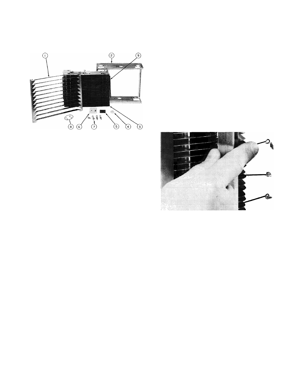
1
— Ionizer Ground Plate
2 — Cell Structure
3 — Charged and Grounded
Collector Plate Assembly
4 — Round Ceramic Insulator
5 — Contact Plate
6 — Rectangular Ceramic Insulator
7 — Bolts
8 — Sheet Metal Screws
9 — Bus Bar
Fig. 15 — Disassembled Cell, Model 31MP
RECTANGULAR INSULATORS, Fig. 15, item 6.
1. Remove the cell structure. See Disassembling
the Plate-Type Cell.
2. Remove the large bolt that holds the insulator
to the end of the plate assembly.
3.
Remove the sheet metal screw holding the
insulator and contact plate, item 5, to the end
of the bus bar, item 9.
4. Lift off insulator and contact plate.
Replacing Ionizer Wires,
Fig. 16 — The following
procedure is recommended for replacing broken
ionizer wires:
1.
Remove ionizer ground plate. See Dis
assembling the Plate-Type Cell.
2. Remove the broken ionizer wire. Be sure no
pieces of the broken wire remain in the cell to
cause shorting.
3. Secure end of new ionizer wire in loop of
bottom ionizer wire spring.
4. Depress top ionizer wire spring with finger as in
Fig. 16.
5.
Secure top end of ionizer wire in loop of
ionizer wire spring while it is depressed.
6.
Inspect wire installation and relieve finger
pressure from ionizer wire spring.
7. Replace ionizer ground plate.
Fig. 16 — Replacing Ionizer Wire