Installation procedure – Carrier 31MC User Manual
Page 2
Attention! The text in this document has been recognized automatically. To view the original document, you can use the "Original mode".
coil clean, reducing maintenance costs. Also, air
coming from the coil will frequently be near
100% relative humidity.
3. The air flow temperature thru the air cleaner
must be within 40 F to 125 F.
Location
— Because air-handling systems vary
greatly in arrangement and style, factors such as
accessibility, ambient temperature ratings, tran
sitions, and other requirements must be carefully
considered.
In crawl space or attic installations (uncondi
tioned space), air cleaner must be insulated the
same as ductwork.
The unit must be readily accessible for periodic
inspection and cleaning of the prefilter and elec
tronic cells to maintain maximum efficiency and
trouble-free operation. A minimum of 30 in. of
clear area should be left in front of the air cleaner
for cell and prefilter removal.
The air cleaner must be installed where the
temperature will be within a 40 F to 125 F range.
Humidifiers
— Location of the system humidifier is
important to the operation of the electronic air
cleaner or mechanical filter.
When an evaporative-type humidifier is used, it
may be installed between the furnace warm air
duct and the return air duct without affecting the
electronic air cleaner.
An atomizing-type humidifier must be installed
downstream from the air cleaner. If the atomizing-
type
humidifier
is
installed
upstream,
high
humidity, salts and minerals will decrease the
efficiency of the electronic cell and cause service
problems or damage the high-efficiency filter
element in the mechanical air filter.
Outdoor Air
— When outdoor air is added to the
return air duct, sufficient heat must be added to
maintain the return air temperature at 40 F mini
mum. Lower temperatures can cause ionizer wire
failure under certain conditions. Two methods are
recommended:
1. Mixing baffles or vanes. When outdoor air is
added, make certain that it is far enough ahead
of the air cleaner to be mixed and warmed
properly. If not, baffles must be installed to
force mixing of the air.
2. Preheat coil. If a large amount of outdoor air is
used, it must be heated. A thermostat should be
used to control the heater. (A strip heater or
hot water coil are typical heaters.)
INSTALLATION PROCEDURE
Remove Filter and Clean Blower Compartment
Before Starting Installation.
1. Remove and discard the old filter if one is used.
2. Thoroughly clean the blower compartment.
The air cleaner cannot remove (firt from the
blower compartment or distribution ducts.
Installation of 31MP Plate-Type or SIMM Media-
Type Air Cleaner
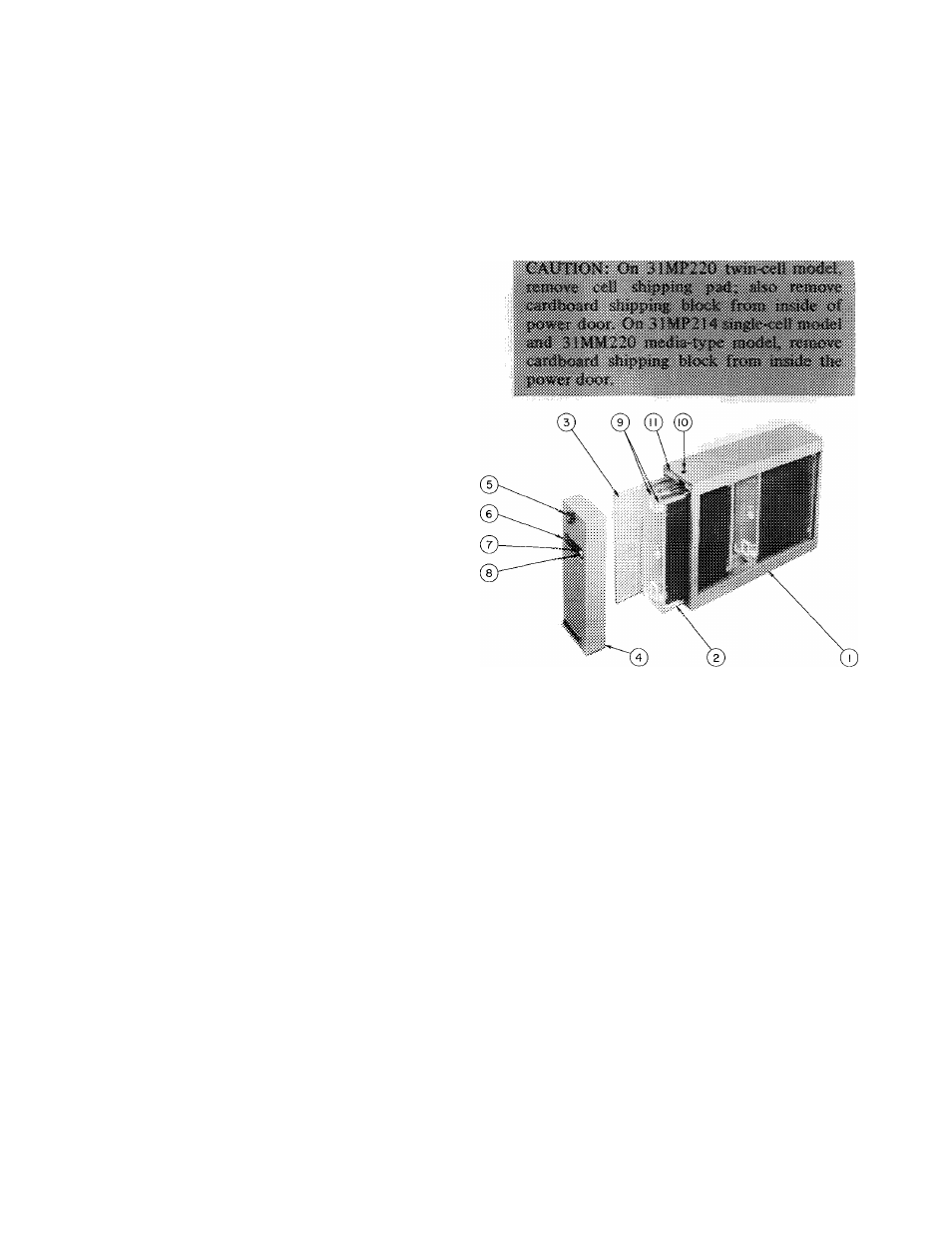
1. Remove power door by turning fastener knob.
Fig. 2, item 5, counterclockwise until power
door is free. Slide out prefilter and air cleaner
cells.
1
— Cabinet
2 - Collector Cell (31 MP)
3 — Prefilter
4 — Power Door
5 — Fastener Knob
6 — Test Button
7 — Indicator Light
8 - ON-OFF Switch
9 — Ceramic Insulators
10 — Opening for Power Supply
11
— Junction Box Cover
Fig. 2 — Electronic Air Cleaner Components,
Model 31 MP
2. Unit can be installed with air flow thru the
cabinet in either direction. No changes to the
cabinet are necessary when reversing the air
flow direction thru air cleaner. See Fig. 3.
3. Apply template, supplied in package, to side of
furnace and prepare the opening in side of
furnace according to instructions on template.
4. Prepare return air duct for installation of unit.
Allow a minimum of 30-in. clearance in front
of power door for servicing.
5. Return air duct should use full cabinet open
ing. Run duct straight into unit. Use an elbow
with turning vanes if duct takes a sharp turn
close to air cleaner inlet. Do not baffle off any
portion of entering air side of air cleaner
When it is necessary to change duct size close
to the air cleaner, use gradual transitions to
reduce turbulence. See Fig. 4.