Fig. 4 — transition from smaller ducts – Carrier 31MC User Manual
Page 3
Attention! The text in this document has been recognized automatically. To view the original document, you can use the "Original mode".
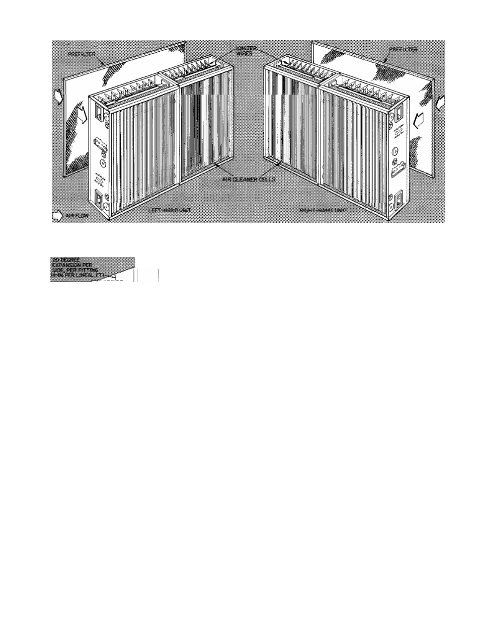
Fig. 3 — Left- and Right-Hand Assemblies
-------L.
RETURN
AIR
DUCT
Fig. 4 — Transition from Smaller Ducts
6. When installing unit at bottom return opening
of an upflow furnace;
a.
Center furnace on air cleaner cabinet and
remove components from cabinet.
b.
Field-fabricated support not required on
Carrier furnaces.
c.
When the furnace is larger or smaller than
the air cleaner, baffle off any mismatch
between furnace and air cleaner with
baffles, included with unit. Additional
support, such as support legs, is recom
mended when furnace overhangs the air
cleaner.
prevefit
» cormt
fr««»
atsl
7. If a filter flag is used to indicate a clogged
filter, install it downstream of cleaner, follow
ing instructions furnished with the filter flag.
8. Seal all joints on downstream side of air
cleaner.
9. Slide prefilter and air cleaner cells into cabinet.
Units are shipped for right-hand installation.
To convert from a right- to a left-hand unit,
reverse the position of the prefilter and the air
cleaner cells in the cabinet as indicated in Fig.
3. Be sure the air flow arrows are pointing to
the direction of air flow thru unit, and the
ionizer wires in the cell are adjacent to the
prefilter. The 31MC220 high-efficiency me
chanical filter does not have a prefilter or
electronic cell. Simply reverse position of filter
element to change from right- to left-hand. An
air flow direction arrow is stamped on the
filter element.
10. Remove junction box cover on 31 MM and MP
units only. Fig. 5, item 1, located below
receptacle, item 2, on top inside of cabinet.
Install strain relief in opening for 120-volt
input supply, Fig. 2, item 10, in top of
cabinet. Connect 120-volt supply pigtails in
junction box with wire nuts provided, and
connect ground wire to green pigtail provided.
Wire supply voltage from fan circuit of system
to have air cleaner operating only when unit
fan is running. See Fig. 6, 7, 8 and 9 for
typical furnace wiring diagrams. All wiring
must
comply
with
applicable
local and
national codes.
11. Replace power door. Turn fastener knob
clockwise
until
power
door
is
securely
fastened, thus ensuring good electrical contact
between power door and unit components.
Diverse installations are shown in Fig. 12.
12. Check over the installation for correct sheet
metal and electrical work.