Carrier 31MC User Manual
Page 10
Attention! The text in this document has been recognized automatically. To view the original document, you can use the "Original mode".
a.
Turn electronic air cleaner on and energize
system fan to power the electronic air cleaner.
b.
Push test button. Snapping sounds (arcing
noise) indicate that air cleaner is working
properly.
c. If no arcing noise is heard, check for continuity
thru resistor, and then check push button
assembly.
STEP 3 - PUSH TEST BUTTON - INDICATOR
LIGHT OEF
a.
Turn on electronic air cleaner and energize
system fan to power the electronic air cleaner.
b. Push test button. Snapping sound indicates that
electronic air cleaner is working properly. Fail
ure is in the indicating light circuit. See Step 9
— Defective Light Circuit.
c. If no snapping sound is heard, go to Step 4.
STEP 4 ~ REMOVE CELLS
a. Turn off blower circuit and remove electronic
cells.
b.
Replace power door and reenergize power
supply. Put switch in “On” position and ener
gize blower.
c. If light comes on now, check cells and top
guide assembly for proper contact. Check surge
resistor. Refer to Step 7.
d. If indicator light does not light, go to Step 5.
STEP 5 - PUSH TEST BUTTON
a. Energize power supply as in Step 1, a and b.
b. Push button. Snapping sound indicates proper
high-voltage output from power supply and
surge resistor. Failure is probably in cells or top
guide assembly or in the light circuit within the
power door. Check cells, light and light circuit.
If light is faulty, replace switch and light
assembly.
c. If there is no arcing or snapping, go to Step 6.
STEP 6 - CHECK LINE VOLTAGE
a. Remove access door and energize blower. Line
voltage to the air cleaner can be determined
using a neon test lamp and inserting prongs into
receptacle on cabinet. If voltage checks low on
the voltmeter, trace wiring back to determine
cause of problem. (Refer to wiring application
diagram.)
b. If voltage checks correctly, open power supply
door by removing the 6 screws from the door
base. Use ohmmeter to check continuity of
low-voltage wiring, taking care to check switch
in both the “Open” and “Closed” position. If
circuitry checks correctly, go to Step 7.
STEP 7 - DISCONNECT SURGE RESISTOR.
ENERGIZE POWER SUPPLY
a. Refer to internal components of the power
door. Fig. 13.
b. De-energize system blower. Remove lug at
output end of power supply and remove surge
resistor from high-voltage circuit.
BLK
WIRE
CONN
<»----------------- ) II5V 60HZ
WHT
Q______ 1 FIELD WIRING
-®----------- FIELD WIRED GROUND
GRN
r
WHT
BLK
INTERLOCK
(DO NOT BYPASS)
0^0-
PWR
SW
RED
VIO
POWER
SUPPLY
PRI
HV-^W
DC
X
>
—o'
PUSH
TEST
ASSY
UNIT
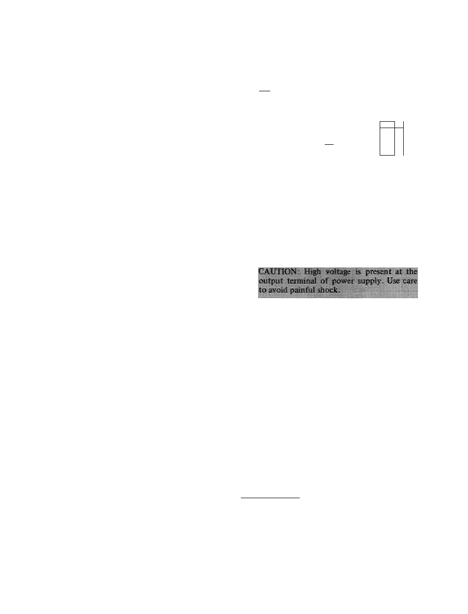
Fig. 17 — Internal Schematic for 31MP and SIMM
Electronic Air Cleaners
c. Using jumper cord and grounding cord, provide
circuitry between plug on power door and
receptacle on cabinet. Attach grounding wire
between power door base and cabinet. See Fig.
18.
d.
Energize system blower and turn switch to
“On” position. Glowing light indicates faulty
surge resistor; replace same. If light still is not
glowing, go to Step 8.
STEP 8 - CHECK OUTPUT OF POWER SUPPLY
a. With blower and electronic cleaner on, measure
output of power supply using voltmeter with
mating high-voltage probe. If output reads
between 6500 to 7500 volts DC, problem is
defective light circuit. Go to Step 9. If output is
low, replace power supply.
STEP 9 - DEFECTIVE LIGHT CIRCUIT
а. With power on, measure voltage at light circuit
terminals on power supply. Output should read
between 90 — 2000 volts. If output is correct,
replace switch and light assembly. If there is no
output, replace power supply.
Component Checks
CHECK ELECTRONIC CELLS
Visual Inspection — Carefully examine the elec
tronic cells. Look especially for:
1. heavy dirt accumulation
2. bent collector plates (plate cleaner)
3. broken ionizing wires
4. dirt accumulation on insulators
5. contact springs — broken or dirty — ionizer and
collector damage
б. deformed pleat grids (media cleaner)
10