Ozone, Service – Carrier 31MC User Manual
Page 6
Attention! The text in this document has been recognized automatically. To view the original document, you can use the "Original mode".
OZONE
The odor of ozone may be noticeable during
operation of an electronic air cleaner. A somewhat
higher ozone generation rate during the first week
or 2 of operation may be caused by sharp edges on
some of the new high-voltage parts. Normal use
dulls these sharp edges in a short time.
The odor of ozone is detectable by an average
person at levels as low as 0.003 to 0.010 parts per
million (ppm). The concentration of ozone pro
duced in a home by an electronic air cleaner ranges
from 0.006 to 0.015 ppm. Average concentrations
of ozone in the air of major cities range from 0.020
to 0.040 ppm and even higher. This is well above
the level produced by an electronic air cleaner.
SERVICE
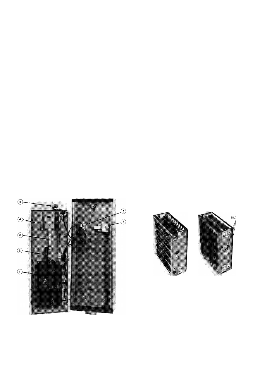
Cabinet Assembly,
Fig. 2, consists of a power door
item 4, which is attached to the cabinet, item 1, by
means of a fastener knob, item 5. Inside the
cabinet are the prefilter, item 3, and the cell, item
2, both of which can be easily slid out of cabinet
for cleaning and service.
Power Door,
Fig. 13, retains all the air cleaning
components inside the cabinet and also contains
the power supply, item 1, which produces high
voltage for the cells. The power door also contains
the surge resistor, item 2, test button, item 7, and
the indicator light and ON-OFF switch, item 3. To
service these components, remove 6 screws from
the ground plate, item 4, on the door and separate
ground plate from door.
1 — Power Supply
2 — Surge Resistor
3 — Indicator Light and
ON-OFF Switch
4
-
5
-
6
-
7
-
Ground Plate
Receptacle
Bus Bar
Test Button
INDICATOR LIGHT AND ON-OFF SWITCH are
both in one unit. Replace complete assembly when
necessary.
1. Disassemble power door. See Power Door.
2. Disconnect wires. Mark wires for reassembly.
3. Compress springs holding light/switch assembly
in door.
4. Pull assembly from front of door.
POWER SUPPLY
1. Disassemble power door. See Power Door.
2. Remove surge resistor connection at the power
supply.
3. Remove 4 sheet metal screws holding the power
supply to the plate.
SURGE RESISTOR is riveted to the bus bar, item
6. The bus bar and surge resistor assembly must be
replaced if the surge resistor is defective.
1. Disassemble power door. See Power Door.
2. Disconnect surge resistor at power supply.
3. Remove screws holding the bus bar.
Cell
— Plate-type and media-type. Fig. 14. The cell
contains the ionizer wires, the ionizer ground plate.
Fig. 15, item 1, and the charged and grounded
collector plate assembly, item 3, of the plate-type
cell.
The plate-type and media-type cleaners are the
same electrically. Physically, however, while the
media-type cell has the same type of ionizer as the
plate-type, a fiber glass pad between a charged grid
and a grounded grid replaces the charged and
grounded collector plate assembly.
Fig. 13 — Power Door
31 MM Media Type
31MP Plate Type
Fig. 14 — Electronic Air Cleaner Cell
DISASSEMBLING THE PLATE-TYPE CELL -
Refer to Fig. 15.
1. Remove 4 sheet metal screws, item 8, holding
the ionizer ground plate, item 1, to the cell
structure, item 2.
2. Lift off the ionizer ground plate.
3. Remove 3 bolts from each end panel. See Fig.
14.