Tab 12 – Carrier 50RQ900291 User Manual
Page 4
Attention! The text in this document has been recognized automatically. To view the original document, you can use the "Original mode".
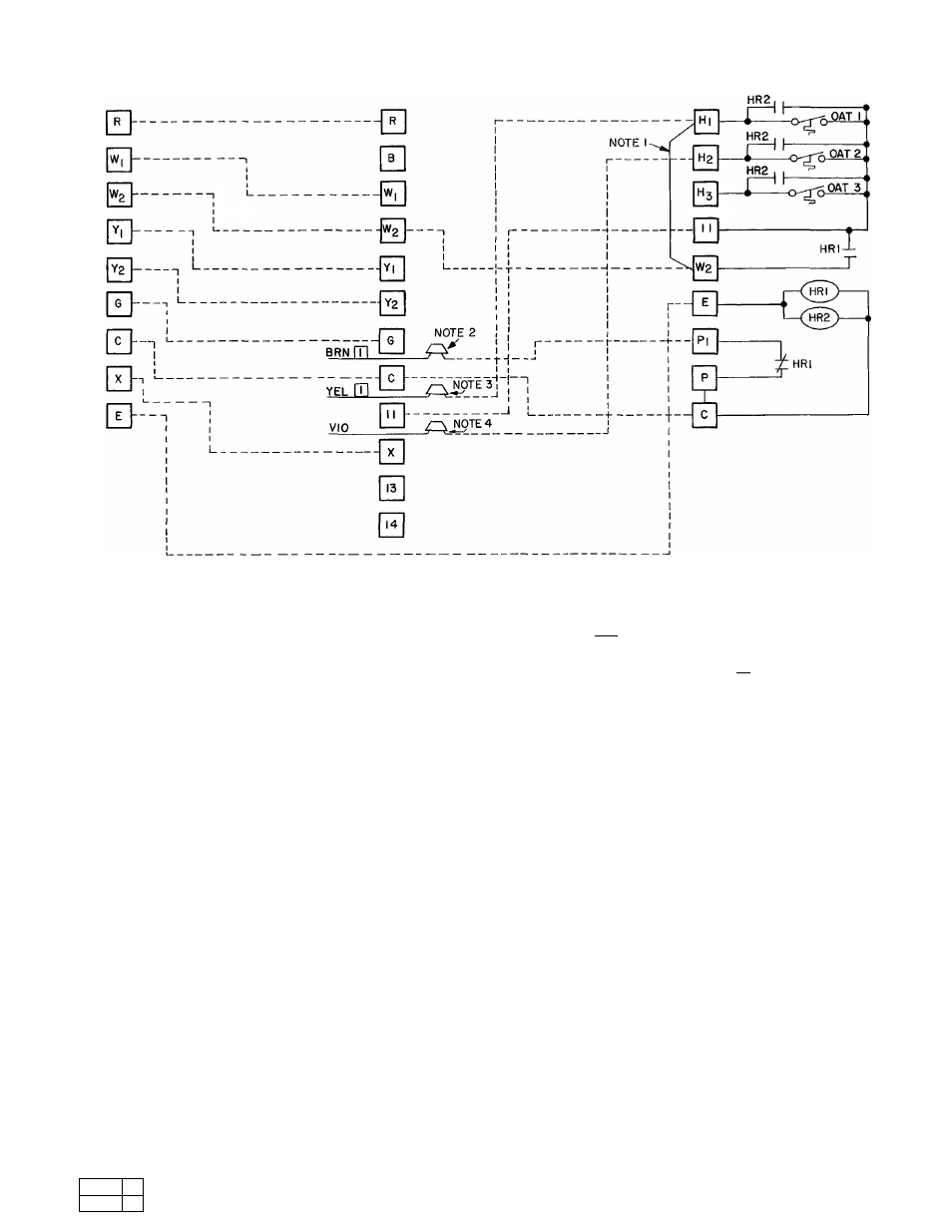
ROOM
THERMOSTAT
BASE UNIT
CONTROL BOX
EMERGENCY HEAT
CONTROL BOX
HR
— Heater Relay
OAT - Outdoor Air Thermostat
Field Splice
------------- Factory Wiring
-------------Field Wii ing
NOTES:
1
Remove jumper wire between HI and W2 in emergency heat control box for
all opeiations
2
Remove brown wire with market ITl from C in base unit control box and field
splice to PI in emergency heat control box for all operations
3
For 1 OAT operation, remove yellow wire with marker pT|ftom terminal 11
in base unit control box and field splice to HI in emergency heat control box
4
For 2 OAT operation, repeat step in Note 3 and remove violet wire from
terminal 11 in base unit control box and field splice to H2 in emergency heat
control box
Fig. 5 — Emergency Heat Wiring Connection Diagram, 50RQ,PQ008/010
Manufacturer reserves the right to discontinue, or change at any time, specifications or designs without notice and without incurring obligations.
Tab 12
Form 50RQ-6SI New
Printed in U S A
3-77
PC 11 1
Catalog No 535—089
Book
1
Tab
5a