Carrier 50RQ900291 User Manual
Page 2
Attention! The text in this document has been recognized automatically. To view the original document, you can use the "Original mode".
^ iC
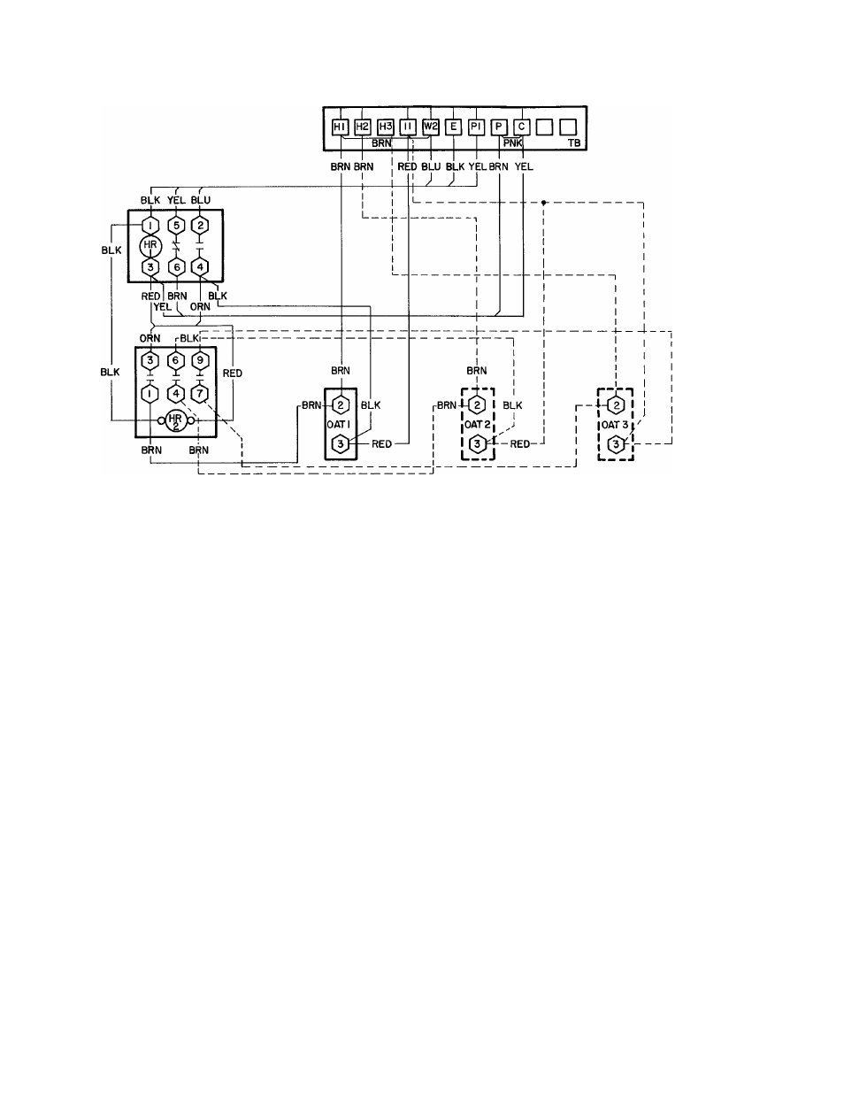
EMERGENCY HEAT CONTROL BOX
FOR CONTROL BOX CONNECTIONS
TO THERMOSTAT AND BASE
UNIT REFER TO FIG. 4 AND 5.
HR — Heater Relay
OAT — Outdoor Air Thermostat
TB - Ter minal Block
_______ Factory Wiring
_______ Field Wiring
□ Terminal Block Connections (Marked)
Component Connections (Marked)
O
Component Connections (Unmarked)
Field Splice
Fig. 2 — Schematic Diagram, Accessory Emergency Heat Control Box, 50RQ,PQ
Outdoor Thermostat Setting
— Set the outdoor
thermostat temperature indicating dial for each
individual installation. If more than 1 thermostat is
used, set additional thermostats in sequence to
allow additional strip heaters to come on as the
outdoor temperature lowers. Before heaters can
come on (except during defrost cycle):
1. The outdoor temperature must be below the
setting of the outdoor thermostat.
2. The room temperature must be 2 F below the
setting of the room thermostat so that the
contacts on the second step of the thermostat
can close. An outdoor thermostat setting that is
higher than necessary results in excess operating
costs; too low a setting prevents heaters from
coming on when they are needed.
• On completion of outdoor thermostat setting,
replace cover on the control box.
Emergency Heat Operation
— If a safety device is
tripped, the compressor locks out thru the oper
ation of the
Signal-LOC^ivi
circuit. When this
occurs, the indicator light comes on at the room
thermostat.
The switch at the room thermostat can then be
moved to EMERGENCY HEAT, bypassing the
compressor and the outdoor thermostat(s) The
second stage of heating at the room thermostat
then activates the resistance heaters to satisfy space
requirements — regardless of outdoor temperature.
If desired, the compressor can be manually locked
out by setting the thermostat to EMERGENCY
HEAT. Under either condition — a tripped safety
device or manual lockout, the indicator light at the
thermostat is illuminated.