Carrier 50RQ900291 User Manual
Page 3
Attention! The text in this document has been recognized automatically. To view the original document, you can use the "Original mode".
ROOM
THERMOSTAT
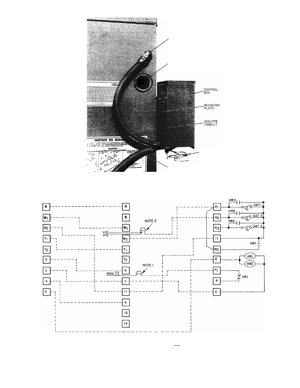
FIELD CONTROL WIRING
(TO BASE UNIT)
HOLE FOR FIELD POWER
SUPPLY OR UNITS WITH
FACTORY INSTALLED
ELECTRIC HEAT OPTION
CAPILLARIES
FIELD CONTROL WIRING
(FROM CONDITIONED SPACE)
Fig. 3 — Accessory Electric Heat Control Box Installation
Condenser End View
BASE UNIT
CONTROL BOX
EMERGENCY HEAT
CONTROL BOX
HR
— Heater Relay
OAT
— Outdoor Air Thermostat
__^ Field Splice
------------ Factory Wiring
------------ Field Wiring
NOTES
1
Remove brown wire with marker [Tlfrom C in base unit control box and field
splice to PI in emergency heat control box for all operations
2
Foi 2 outdoor air thermostat operation, remove both violet wires from W2 in
base unit control box and field splice to H2 in emergency heat control box
Fig. 4 — Emergency Heat Wiring Connection Diagram, 50RQ,PQ006
- SYNERGY 38YD (9 pages)
- 38YCX (8 pages)
- 50TFQ008-012 (56 pages)
- INFINITY 50XT-A (4 pages)
- 38QN (8 pages)
- 50CR (32 pages)
- 542D060 (18 pages)
- 50LJQ008 (24 pages)
- 38HQ (20 pages)
- AIR COOLED SPLIT SYSTEM 38AQS008 (20 pages)
- XPOWER 38VYX130 (14 pages)
- 38E (20 pages)
- AQUAZONE PTV (64 pages)
- AQUAZONE 50PCH (52 pages)
- 38QP024 (6 pages)
- 38BYC (8 pages)
- XPOWER 38VYX050 (14 pages)
- AQUAZONE 50QE900-250FS (8 pages)
- AQUAZONE RDS006-060 (44 pages)
- 50YX (20 pages)
- 50VQ (14 pages)
- 50HQ (14 pages)
- 50MQ (12 pages)
- 10 SEER SPLIT-SYSTEM 38YCW (8 pages)
- 38AUQ (36 pages)
- WEATHERMASTER 2000 (9 pages)
- COMFORT 25HCS (6 pages)
- 50DQ (6 pages)
- 38AC (6 pages)
- 50RTG (28 pages)
- AQUAZONE 50RTP03-20 (60 pages)
- COMFORT 50EZ-A (6 pages)
- 38AYB (4 pages)
- 50YQ (16 pages)
- 50ET (14 pages)
- COMFORT SERIES 25HCB3 (8 pages)
- 38QF (18 pages)
- WEATHERMASTER III 38HQ (19 pages)
- GT-PX (56 pages)
- 50QQ (16 pages)
- AQUAZONE 50VQP084-300 (48 pages)
- 50JS (4 pages)
- 50JS (28 pages)
- 38AQ024 (14 pages)
- 38QB (20 pages)