Carrier 28QX User Manual
Page 27
Attention! The text in this document has been recognized automatically. To view the original document, you can use the "Original mode".
leaving water header in approximately 60-
second intervals. Using this method will
remove most of water in coil circuits.
d.
See fan section, electric heater, or the
compressor section Installation, Start-Up
and Service Instructions for scheduled
maintenance.
STORAGE TANK
e. As specified in the Start-Up Instructions, an
inhibitor must be added to the water in the
storage tank to prevent corrosion. Since this
is an open system, it is very important that
the effectiveness of the inhibitor is main
t a i n e d .
(See
Inhibitor
Manufacturer’s
Instructions).
2. Outdoor components
The 38HQ940/960 coil should be cleaned
annually or as often as required.
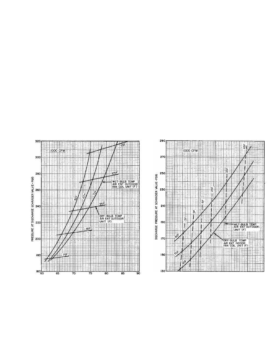
REFRIGERANT CHARGING - The 38HQ out
door fan coil unit contains correct operating charge
for complete system. Refer to 38HQ Unit Installa
tion, Start-Up and Service booklet for refrigerant
charging method details. Cooling cycle charging
charts and heating cycle operation check charts for
38HQ/28QX systems are included in this booklet.
Fig. 31 thru 36.
CAUTION: Rapid, removal of Refrigeran.t-22
charge from heat pump system can <3ro;p pre.s-
sure and lower temperature and can cause water
in tire Tri~X coil to freeze and split coil tubes.
When necessary for servicing, remove ciiarge
very slowly to minimize possibility of freeze
dajnage.
PRESSURE AT SUCTION SCHRADER VALVE-PSIG
20
30
40
50
60
SUCTION PRESSURE AT SCHRADER VALVE-PSIG
70
Fig. 31 - 38HQ127/38HQ940 with 28QX036
Cooling Cycle Charging Chart
Fig. 32 - 38HQ127/38HQ940 with 28QX940
Heating Cycle Operation Check Chart
27