Carrier 28QX User Manual
Page 17
Attention! The text in this document has been recognized automatically. To view the original document, you can use the "Original mode".
#
Any field installed run of horizontal tubing in
the collector loop must be pitched downward a
minimum of 1/4-in. per foot. A pitch greater than
1/4-in./ft, such as 3/8-in./ft or 1/2-in./ft, is accept
able and better than 1/4-in./ft. This pitch require
ment is critical to the installation because failure to
incorporate this requirement will result in system
failure. A l/4-in./ft pitch (min.) and specified
tubing sizes allow positive liquid drainage.
The size of tubing to be used in the “collector
supply” leg of the loop is specified by Carrier.
Both “collector supply” and “collector return”
legs must be insulated.
Add a field procured and installed component
to the “collector supply” leg of the loop — an
ASME approved pressure relief device with a 50
psig set point (not required on plain water system).
Install in a T-joint in the conditioned space side of
the “collector supply” leg. The device should not
project into the supply leg pipe (see detail A of
Fig. 20).
wa,TER
OUT N
2SQX
SUPPt-Y
SUPPLY
■'I
TERMIMATE
8£L0W
LOWEST
WATE3R LEVEL
RETUSN
, , , ,
JU
|! ¡[WATERin-
, j
eXPAiiSlON
TANK
STORAOE
SUPPLY ■
Fig. 21 — Tri-X Coil Piping Loop on Glycol System
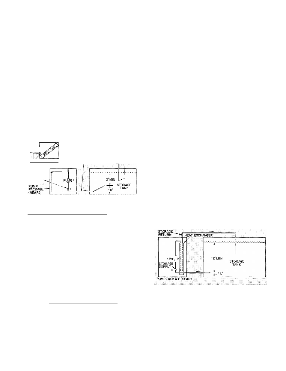
28QX (Tri-X) Coil Loop (Fig. 21) — The loop
begins in the storage tank with a pipe at the
bottom of the tank. This pipe exits the tank
bottom and goes to the rear of the pump package
to the left-hand stub labeled “storage supply.” The
loop continues thru a pump and out of the pump
package thru the “28QX supply” stub. The loop
continues to the 28QX coil where it enters at the
“water-in” stub. After traveling thru the coil, the
loop exits at the “water-out” stub of the coil and
returns thru the top or bottom of the storage tank.
(This loop must terminate below the lowest water
level.)
The pipe size and allowable lengths of this loop
are listed below.
ALLOWABLE PIPE LENGTHS
Pipe O.D. (in.) Maximum Equivalent Length (ft)
7/8
1
1
-
1/8
60
120
240
The pipe length listed is for the entire loop length.
A value of 5 equivalent ft should be used for the
pipe inside the pump package. There is no mount
ing height restriction for the 28QX coil since it
operates in a closed loop system. There are,
however, other restrictions.
a. The termination points of the loop (in storage
tank) must always be below the lowest water
level in the storage tank for the loop to be a
closed system.
b. The beginning point for the pipe that enters the
“storage supply” stub on the pump package
must always be at least 2 ft below the lowest
water level in the storage tank but not less then
6 in. from bottom of tank.
c. It is recommended that the 28QX coil be the
highest part of the loop. This is accomplished
by routing the supply and return pipes below
the coil height level. The reason for having the
28QX coil at the highest point is to make the
air bleed valve in the coil effective. If it is not
possible to route the return and supply lines
below the coil, an air bleed valve (similar to the
one found on the 28QX coil water header) will
have to be installed at the highest point in the
loop.
d. If the 28QX coil is mounted more then 6 ft
above the water level in the storage tank, a
special fill-up procedure will have to be
followed. Details can be found in the Start-Up
Instructions section. However, this procedure
will require a booster pump and booster pump
inlet fitting added to the 28QX supply line
between the pump package and 28QX coil. It
will therefore be necessary to add the booster
pump fitting when installing the 28QX supply
pipe. Refer to the Start-Up Instructions for
details concerning the type of fitting to be
used.
Fig. 22 — Heat Exchanger Piping Loop
on Glycol System
Heat Exchanger Loop (Fig. 22) — This loop begins
in the storage tank. A pipe leaving the bottom of
the storage tank travels to the rear of the pump
package to the right stub labelled “storage supply.”
The loop continues inside the pump package thru
the pump and heat exchanger and exits the unit at
the “storage return” stub. From here, the loop
returns to the top or bottom of the storage tank
(should be below the lowest water level).
17