Carrier 28QX User Manual
Page 10
Attention! The text in this document has been recognized automatically. To view the original document, you can use the "Original mode".
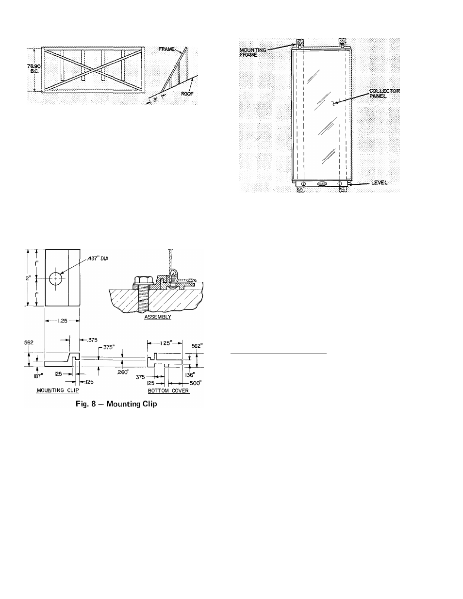
Fig. 7 — Typical Collector Mounting Frame
MOUNT THE COLLECTORS on completed frame
or sleepers. Lasten in place with four mounting
clips supplied with each collector. Use 2 clips on
each end of the collector. See Fig. 8. Each clip has
a .437-in. diameter hole to accept a field supplied
mounting screw. Use a level to align the collectors
exactly parallel to the horizontal plane, Fig. 9.
NOTE: There is no fixed top or bottom to a
collector. It can be installed either way,
although it may be preferable to install so
nameplate can be read.
NOTE: Supply and return piping must be sloped
Fig. 9 — Collector Panel Leveling
MAKE PIPING CONNECTIONS - Attach supply
and return piping headers and lines to collectors.
Piping supply line size is specified by Solar CLIC.
Return line is 2-1/8 in. O.D. on all systems. See
Fig. 10. The headers can be completely pre
fabricated.
Determine
distance
between
the
collector inlet connections and outlet connections
(35-in. if panels are butted up to each other). Make
headers with regularly spaced T-sections to mate
with the inlet and outlet of the collector array.
Acquire two 3/4-in. MPT to 3/4-in. sweat
copper fittings for each collector. To each fitting,
solder (95-5) a 3/4-in. copper pipe stub of appro
priate length to maintain a minimum vertical
1/4-in. slope/ft of header. It might be necessary to
bend the copper stubs to maintain this vertical
slope. Thread the fittings with copper stub
attached into the collectors and solder the headers
onto the stubs (Fig. 10). Solder the supply and
return lines in place. Install a tee with a pressure
relief valve between the leaving header and 2-1/8
in. return pipe. Use an ASME approved pressure
relief device with a 50 psig set point and a manual
release lever. (See Leak Testing below.)
If it is necessary for return and supply pipes to
penetrate the roof, install a pitch pocket to seal the
opening.
Install the Collector Sensor on an interior collector
panel after headers have been soldered in place.
Sensor location and method of attachment is
described on pg 15.
LEAK TEST THE COLLECTOR ARRAY ^ Using
city or well water with a minimum pressure of 30
psig, leak test the collectors and piping as follows;
;a. Soft solder (50-50) a temporary cap or end of
2-1 /8 in. collector return line.
b. Attach water supply line to collector supply
pipe.
c.
Fill collector array with water using release
lever on pressure relief valve (Fig. 10) to bleed
air from collector system. If relief valve does
not have a manual release lever, temporarily
replace the relief valve with an air bleed valve.
d. Leave water pressure on to system and check
collectors and piping for leaks per local codes.
e.
If leaks occur, drain water from system by
removing water pressure source. Repair leak
and repeat steps b, c, d and e.
f.
Using a tubing cutter, remove temporary cap
from 2-1/8 in. return line. (This liiie will be
filled with water.)
10