Carrier 28QX User Manual
Page 14
Attention! The text in this document has been recognized automatically. To view the original document, you can use the "Original mode".
LOCATE AND INSTALL THERMISTOR SEN
SORS AND AQUASTAT BULBS - Located in the
low voltage terminal block compartment of the
control box are 2 thermistor sensors and 3 bulb
wells, Fig. 18.
Two of the bulb wells are to be used with the
aquastat bulbs located on the control box in pump
package, Fig. 12. These wells are to be inserted in
the storage tank so that the aquastat bulbs are
located at the same level in the storage tank as the
outlet to the Tri-X pump. The aquastats are bulb
and capillary refrigerant charged sensors. The
capillary tubes are 20 ft long. Consequently, the
pump package should be placed with this restric
tion in mind.
If it is necessary, the aquastats may be removed
from the control box and mounted close to the
storage tank. If this approach is taken, 14 gauge
wire should be used to connect the aquastat to the
appropriate wires out of the control box.
Thermistor Sensor Mounting — Mount sensors so
that good thermal contact is maintained. A small
amount of G.E. insulgrease #640 (field supplied)
between the sensor and the interior tube of the
solar panel array and also in the well used on the
storage tank sensor is recommended to improve
thermal contact.
Storage Tank Thermistor — The thermistor is not
submersible and should be placed in the remaining
bulb well at the same level in the storage tank as
the outlet to the collector pump.
#
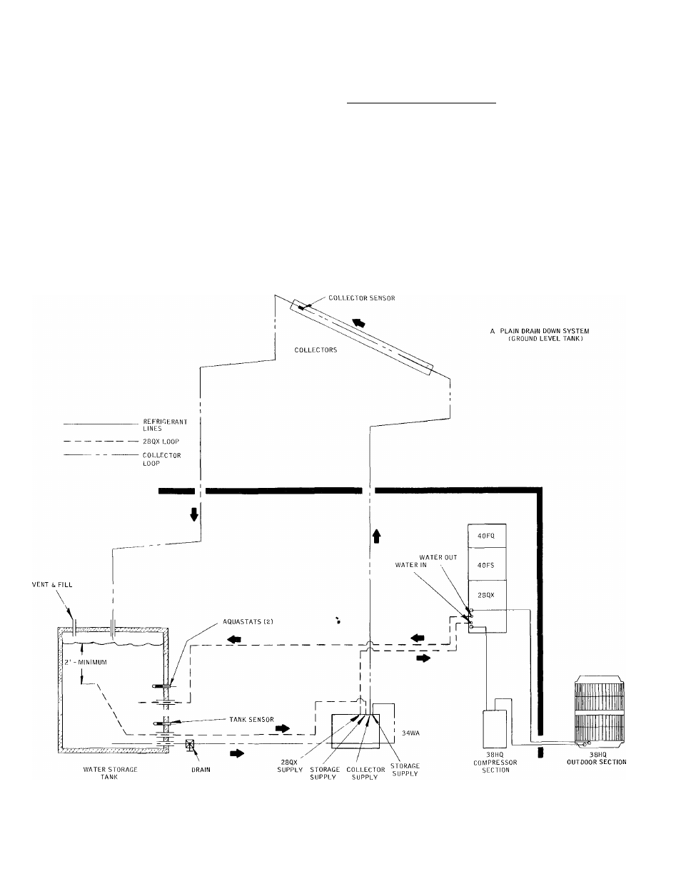
All water supply lines leaving storage must be more than 6-in from bottom of tank but no closer than
2 ft from lowest water level
Fig. 16 — Typical Plain Water System Piping Diagram
14