Carrier 28QX User Manual
Page 18
Attention! The text in this document has been recognized automatically. To view the original document, you can use the "Original mode".
The pipe diameters and the allowable lengths
for this loop are listed below.
ALLOWABLE PIPE LENGTHS
Pipe O.D. (in.) Maximum Equivalent Length (ft)
7/8
1
1
-
1/8
25
50
100
A value of 8 equivalent ft should be used for the
pipe length inside the glycol pump package.
It is advisable to terminate the storage return
pipe below the lowest water level in the storage
tank. This will make this loop a closed loop and
will assure that no air could infiltrate the loop. It is
important that the height of the return pipe above
the storage water level not exceed 6 feet. If it is
necessary to do so, a special fill-up procedure that
is found in the Start-Up Instructions will have to
be followed, pg 23.
LOCATE AND INSTALL THERMISTOR SEN
SORS AND AQUASTAT BULBS - Located in the
low voltage terminal block compartment of the
control box are 2 thermistor sensors and 3 bulb
wells, Eig. 18.
Two of the bulb wells are to be used with the
aquastat bulbs located on the control box in pump
package. Fig. 12. These wells are to be inserted in
the storage tank so that the aquastat bulbs are
located at the same level in the storage tank as the
outlet to the Tri-X pump. The aquastats are bulb
and capillary refrigerant charged sensors. The
capillary tubes are 20-ft. long. Consequently, the
pump package should be placed with this restric
tion in mind.
All water supply lines leaving storage must be more than 6--in. from bottom of tank, but no closer than
2 ft from lowest water level.
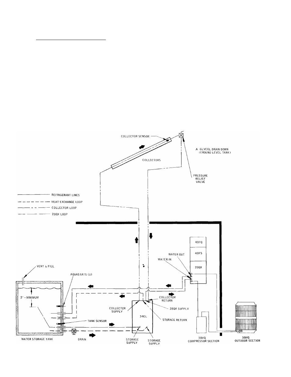
Fig. 23 — Typical Glycol System Piping Diagram
18