R820 scr power controller, Set vernier ratio potentiometer to 100 – Viconics R850 Installation Guide User Manual
Page 6
LIT-R850V-E03
6
Control Switch #2 Off
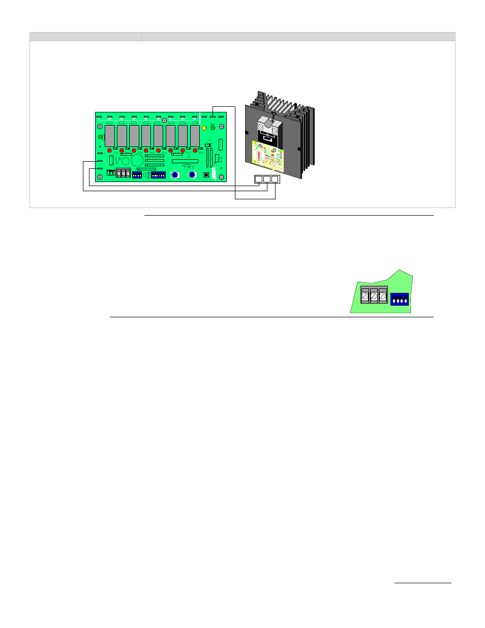
0 to 10 Vdc analog output to activate R820 SCR power controller
Set the R820 SCR power controller to accept a 0 to 10 Vdc control signal input
Switch #1, #2 & #3 Off Switch #4 On
The intensity of the green status LED on the master unit is proportional to vernier output
For more information, please refer to the R820 service manual
SLAVE APPLICATION SECTION
When using a unit for slave applications, it is important that the proper adjustments & setting be made to the unit for proper
operation of the system.
The yellow LED near the vernier output connector is proportional to the vernier output of the master unit ( 0 to 5 Vdc ).
On the slave unit:
•
Set vernier ratio potentiometer to 100%
•
Set interstage delay potentiometer to the same value as the master unit
•
Set all control signal INPUT dip switch to OFF
TEST MODE BUTTON
The test mode button can be used to verify if the number of stage have been configured properly.
1. Press and hold the button for 3 to 4 seconds.
2. If a slave unit is used, press & hold the 2 units button simultaneously
3. All the selected stage will come on, one after the other until all selected number of stages are all on.
4. There is a delay of approximately 5 second between each step activation.
5. When all selected stage are on, they will stay on for approximately 30 seconds before shutting down.
Powering up the R850V controller while holding down the test button will by-pass the interstage delay for 10 minutes. During that
period, the unit will respond to a changing signal input very rapidly. Also hold down slave test button on start-up if a slave unit is
used. After that 10 minute period, the unit will function normally with the interstage delays active
Viconics Electronics Inc. 9245, Langelier Blvd, St-Leonard, Quebec, Canada H1P 3K9
www.viconics.com
JU
N
E
9
9
R
EV.
1
T
EST
RA
T
IO
(%
)
100
200
150
VR
2
1
2
3
1 2
3
ON
4
1
2
3
ON
4
5
6
I N P U T
C O N T R O L
001
-010
2
DE
L
A
Y
(s
)
120
60
30
90
1
23
CO
M
V
S
C8
C7
C6
C5
C4
C3
C2
C1
C
PO
W
E
R
1 2 3
R820
SCR Power Controller
1
2
3
1
2 3
ON
4
I N P U T