R850v-8, 24 vac contactor coils – Viconics R850 Installation Guide User Manual
Page 4
4
JU
N
E
9
9
R
EV.
1
TE
S
T
RAT
IO
(%
)
10
0
20
0
15
0
VR
2
1
2
3
1
2 3
ON
4
1
2 3
ON
4
5 6
I N P U T
C O N T R O L
00
1-
0
1
02
DE
L
A
Y
(s
)
12
0
60
30
90
1
23
CO
M
V
S
C8
C7
C6
C5
C4
C3
C2
C1
C
PO
W
E
R
7.075"
0.325"
3.450"
0.250"
3.050"
3.675"
2.700"
0.225"
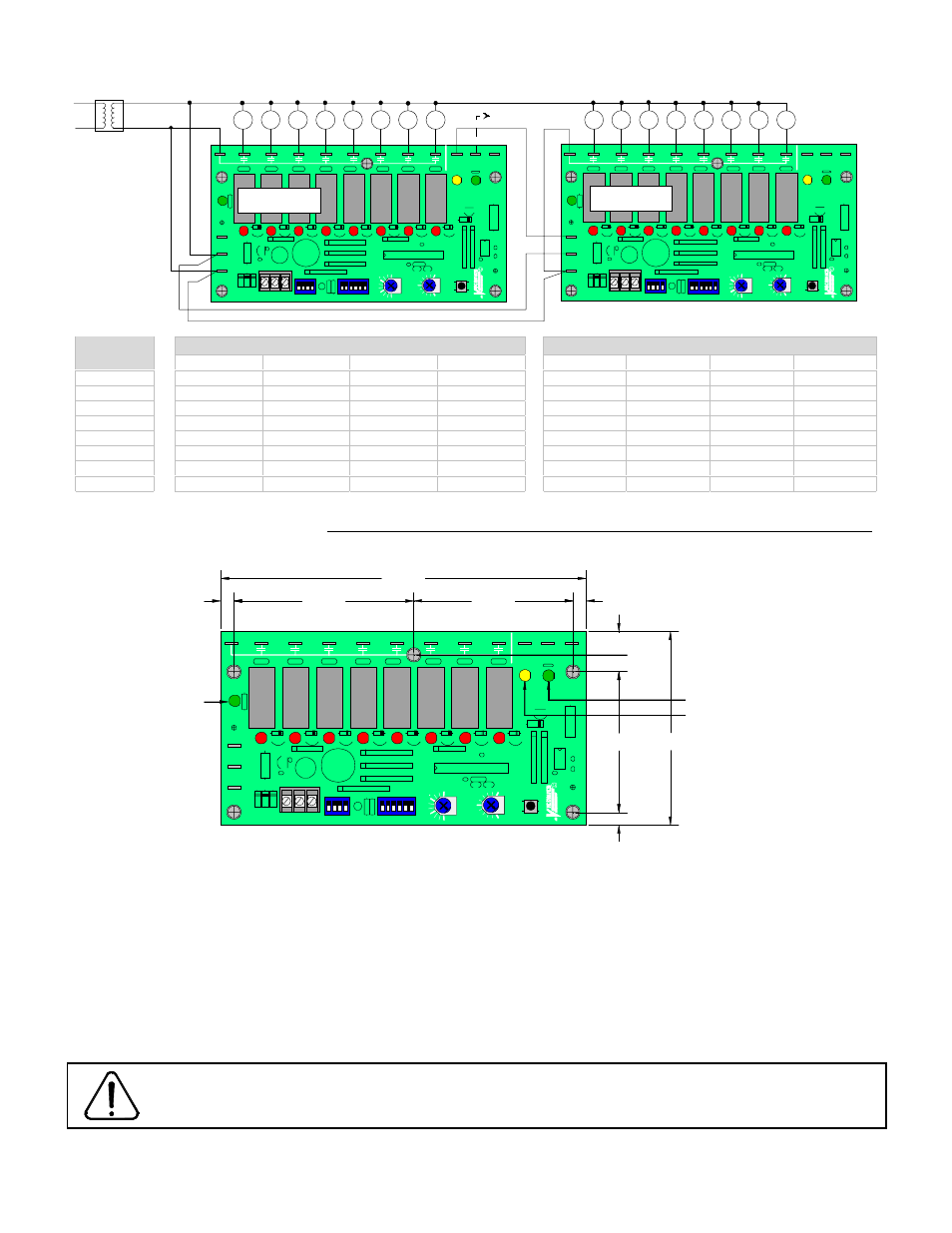
Vernier output green LED
Slave output yellow LED
Power indicating
green LED
0.325"
0.425"
•
16 STAGE APPLICATION
R850V-8 MASTER UNIT, R850V-4 SLAVE UNIT ( See also slave application section at the end )
R850V-8 Master Unit Control Switch
R850V-8 Slave Unit Control Switch
Number
of stage
Switch #3
Switch #4
Switch #5
Switch #6
Switch #3
Switch #4
Switch #5
Switch #6
9
Off
Off
Off
On
Off
Off
Off
Off
10
On
Off
Off
On
On
Off
Off
Off
11
Off
On
Off
On
Off
On
Off
Off
12
On
On
Off
On
On
On
Off
Off
13
Off
Off
On
On
Off
Off
On
Off
14
On
Off
On
On
On
Off
On
Off
15
Off
On
On
On
Off
On
On
Off
16
On
On
On
On
On
On
On
Off
The intensity of the yellow status LED on the master unit is proportional to the slave output.
R850V DIMENSIONS & INSTALLATION
Install on the mounting plate on the electrical cabinet using five #6 pan head metal screw. Do not over torque the screws to prevent
damage to the board. Specifications and equipment are subject to change without prior notice.
All R850V series controls are for use only as operating controls. Whenever a control failure could lead to personal
injury and/or loss of property, it becomes the responsibility of the user to add safety devices and/or alarm system
to protect against such catastrophic failures.
JU
N
E
9
9
R
EV.
1
TE
S
T
RAT
IO
(%
)
10
0
20
0
15
0
VR
2
1
2
3
1
2
3
ON
4
1
2
3
ON
4
5
6
I N P U T
C O N T R O L
00
1
-0
1
02
DE
L
A
Y
(s
)
12
0
60
30
90
1
23
CO
M
V
S
C8
C7
C6
C5
C4
C3
C2
C1
C
PO
W
E
R
JU
N
E
9
9
R
EV.
1
TE
S
T
RAT
IO
(%
)
10
0
20
0
15
0
VR
2
1
2
3
1
2
3
ON
4
1
2
3
ON
4
5
6
I N P U T
C O N T R O L
00
1
-0
1
02
DE
L
A
Y
(s
)
12
0
60
30
90
12
3
CO
M
V
S
C8
C7
C6
C5
C4
C3
C2
C1
C
PO
W
E
R
24 Vac contactor coils
24 Vac contactor coils
R850V-8
C1
C2
C3
C4
C5
C6
C7
C8
C9
C10
C11
C12
C13
C14
C15
C16
R850V-8
Use vernier output of master
if vernier control is required
Note: Set all control signal INPUT dip switch to OFF on slave unit.