R850v-4, 24 vac contactor coils – Viconics R850 Installation Guide User Manual
Page 2
2
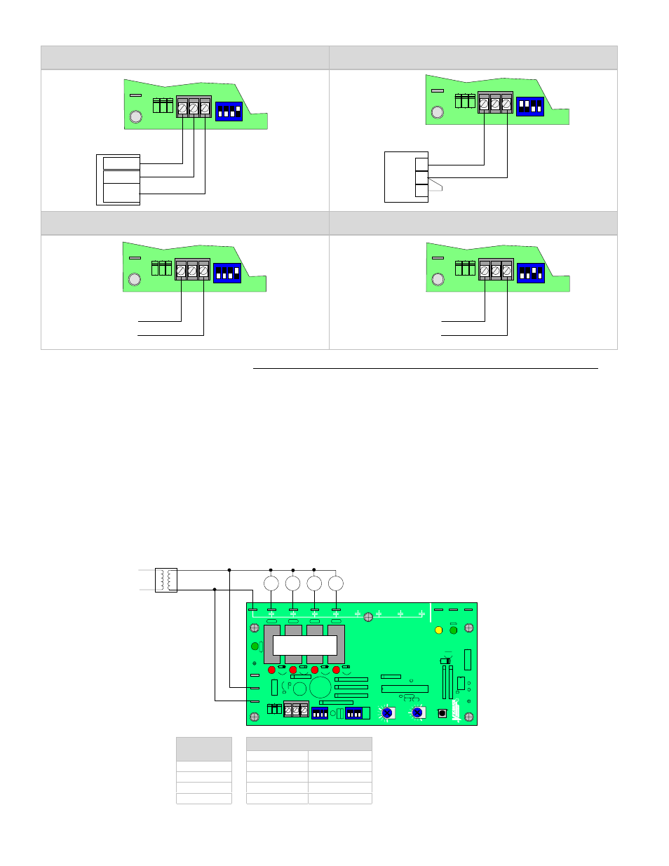
2 To 10 Vdc Or 0 To 10 Vdc Stand Alone Thermostat
( Power To The Thermostat Is Supplied By The R850V )
0 To 135
Ω Stand Alone Thermostat
2 To 10 Vdc Or 0 To 10 Vdc From D.D.C.
Building Automation System
4 To 20 mA From D.D.C.
Building Automation System
24 VAC POWER & RELAY OUTPUT WIRING
The wiring diagrams are for the R850V-8 models with 8 outputs. The wiring for the R850V-4 is the same except that the unit only
has 4 outputs.
Terminals
Screw terminal & connector #1
Common
Screw terminal & connector #2
24 Vac
Screw terminal & connector #3
Control Signal input
• It is not necessary to ground any leg of the transformer to earth with the controller card.
• The controller uses internally a half wave rectifier bridge. On 0 to 10 Vdc control signal, the reference of the control signal is the
Common of the power supply of the SCR controller card.
• Use a Class 1 ( properly fused ) or Class 2, CSA or UL recognized transformer.
•
4 STAGE APPLICATION
R850V-4
R850V-4 Control Switch
Number
of stage
Switch #3
Switch #4
1
Off
Off
2
On
Off
3
Off
On
4
On
On
Common
24 Vac
0 to 10 Vdc
output
2 Vdc = 0% capacity
10 Vdc = 100% capacity
1
2
3
1
1
2
3
ON
4
I N P U T
R
W
B
0 Ohms = 0% capacity
135 Ohms = 100% capacity
1
2
3
1
1
2
3
ON
4
I N P U T
-
+
2 Vdc = 0% capacity
10 Vdc = 100% capacity
1
2
3
1
1
2
3
ON
4
I N P U T
4 mA = 0% capacity
20 mA = 100% capacity
-
+
1
2
3
1
1
2
3
ON
4
I N P U T
J
UNE
9
9
R
EV.
1
TE
S
T
RAT
IO
(%
)
10
0
20
0
15
0
VR
2
1
2
3
1
2 3
ON
4
I N P U T
C O N T R O L
00
1-
0102
DE
L
A
Y
(s
)
12
0
60
30
90
12
3
CO
M
V
S
C8
C7
C6
C5
C4
C3
C2
C1
C
PO
W
E
R
1
2
3
ON
4
C1
24 Vac contactor coils
C2
C3
C4
R850V-4