R810 – Viconics R850 Installation Guide User Manual
Page 5
5
LIFO / FIFO ADJUSTMENT
The R850V series features 2 different staging sequences:
•
LIFO
LAST IN FIRST OUT ( CONTROL SWITCH #1 OFF, FACTORY DEFAULT )
This is the regular mode, Stage #1 will always be the first to energize and the last stage to de-energize
•
FIFO
FIRST IN FIRST OUT ( CONTROL SWITCH #1 ON )
In this mode, the stages are rotated to ensure a more uniform wear of the contactors and elements. For example, on an increase in
demand, stage 1 will be energized following by stage 2, etc. On a decrease in demand, stage 1 will de-energized first followed by
stage 2, etc.
Please verify that if this mode is enabled, the manufactured product still complies with active codes and regulations.
VERNIER STAGE SELECTION AND WIRING
The Viconics R850V series step controller has an integrated vernier control output. This output will give a precise and full
modulation of the load from 0 to 100% of the total capacity of the unit. If a master slave application is used, always connect the
vernier output of the master unit.
ADJUSTMENTS
Functions of the units can be configured with six dip switch and 2 potentiometers.
Interstage delay potentiometer setting
A potentiometer is used to adjust the interstage delay from 30 seconds up 120 seconds.
This delay is active in 3 ways.
•
Minimum time delay between each step activation when the control signal rises
•
Minimum ON time when the step is activated
•
Minimum time delay between each step de-activation when the control signal drops
Vernier stage ratio
A potentiometer is used to adjust the vernier stage ratio from 100% to 200% capacity of the other on/off
stage capacity.
RATIO SETTING ( See also slave application section at the end )
First adjust the vernier stage ratio potentiometer. This will insure a smooth capacity rise of the total load.
Example 1:
The total unit has 100 kW divided in 10 equal stage of 10 kW.
If only 10 kW is used as the modulating stage, then the heater would have 9 on/off mechanical stage plus
one modulating stage. This modulating stage has the same value as all the other stage. Adjust the vernier stage ratio
potentiometer to 100%.
Example 2:
The total unit still has 100 kW divided in 10 equal stage of 10 kW.
If 20 kW are used as the modulating stage, then the heater would have 8 on/off mechanical stage plus one modulating stage.
The modulating stage has twice the value as all the other stage. Adjust the vernier stage ratio potentiometer to 200%.
•
TYPE OF VERNIER STAGE SETTING
The vernier stage output can be configured to operate either as a:
•
Vdc pulsed output to activate an R810 power module
•
0 to 10 Vdc analog output to activate an R820 SCR power controller.
•
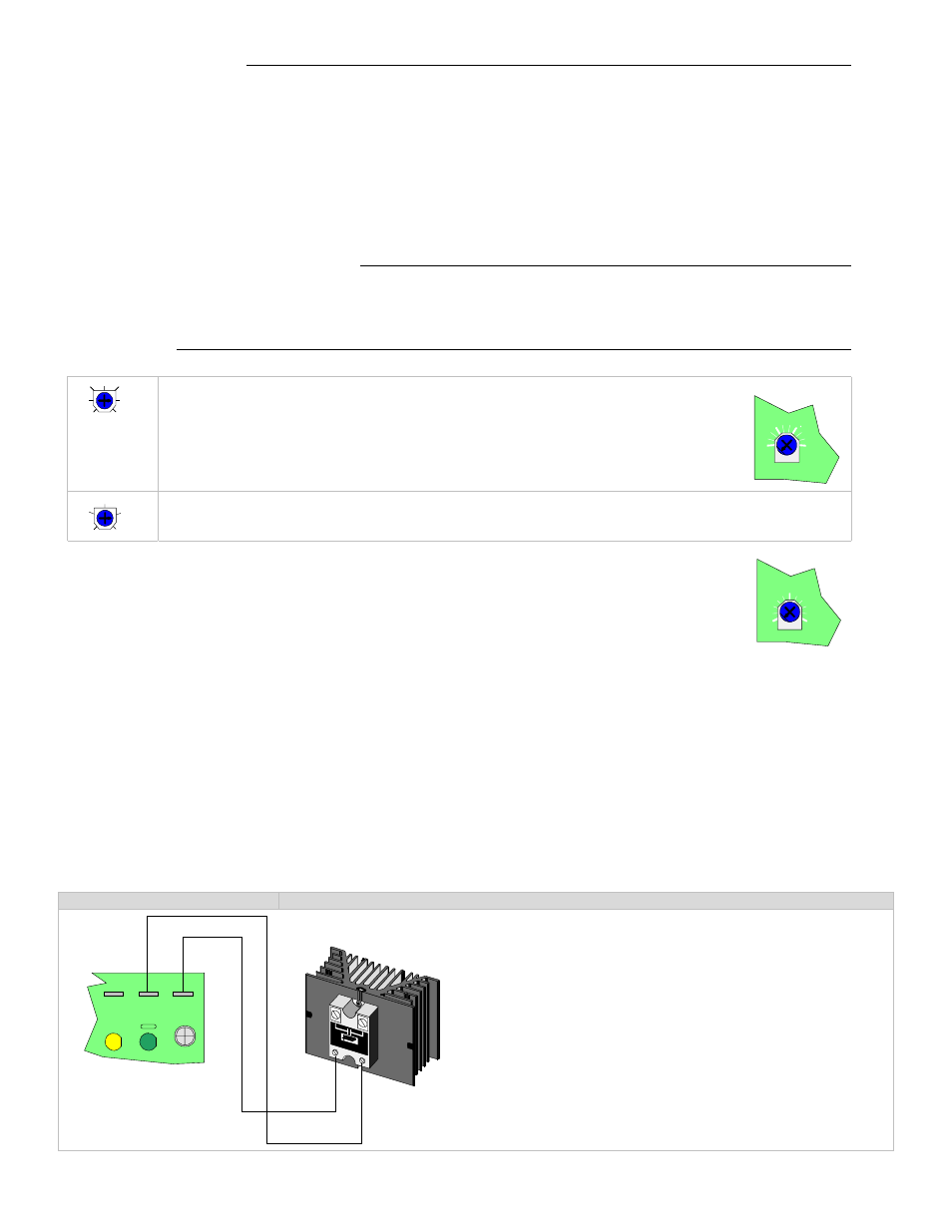
VERNIER STAGE WIRING
Control Switch #2 On
Vdc pulsed to activate R810 power modules
Do not wire more than six R810 power module on the
vernier stage output
Respect the polarity between the R850 step controller
board an the R810 power modules
Connect V to +
Connect COM to -
The green status LED on the master unit will cycle at
the same rate as the time proportioning vernier output
For more information, please refer to the R810 service
manual
RATIO(%)
100
200
150
VR2
CO
M
V
S
+
-
R810
100
200
150
125
175
30
120
75
45
60
90
105
DELAY(s)
120
60
30
90