Viconics VWZS Application Guide User Manual
Page 36
36
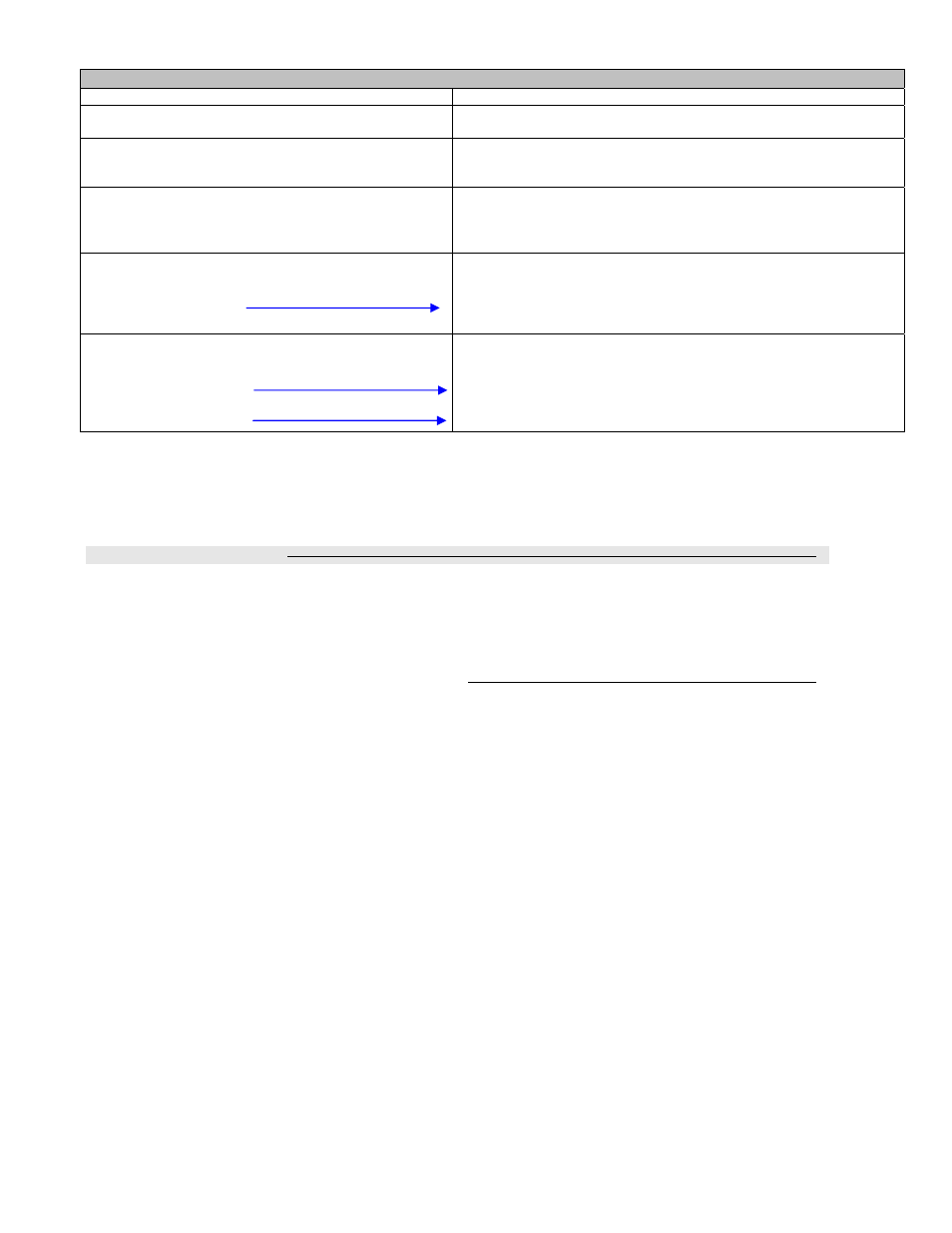
VZ72 Adapter LED Status Indicators
1 x 200ms short blink
Power on
2 x 200ms short blinks
Power on
Communicating with controller base
3 x 200ms short blinks
Power on
Communicating with controller
There is connectivity to wireless network
4 x 200ms short blinks
Power on
Communicating with controller
There is connectivity to wireless network
VZ76 or VWG / Jace-Driver is communicating with Wireless controller
4 x 200ms short blinks
and
1 x 1500ms long blink
Power on
Communicating with controller
There is connectivity to wireless network
VWG / Jace-Driver is communicating with Wireless controller is also
added to the VWG / Jace-Drive database
4 x 200ms short blinks
and
1 x 1500ms long blink
and
1 x 3000ms long blink
Power on
Communicating with controller
There is connectivity to wireless network
VWG / Jace-Driver is communicating with Wireless controller is also
added to the VWG / Jace-Drive database
Wireless communication with VZ76 RTU controllers active
The 3000ms status flag is enabled when the VZ72xx zone controller successfully reads the required
functional data points from its attached master VZ76xx RTU controller: Occupancy, Outdoor temperature,
zone sequence, etc….
5) System Commissioning
If proper system operation is expected, then proper system commissioning should be done at all levels.
A zoning system has a huge dependency on the demand and response being fully functional both at the
RTU and the zone level.
5A) Proper Commissioning of the Zone Controllers
At the zone level, care should be taken to insure that the following criteria(s) are met:
-
Proper sizing of the VAV zone damper and the design of the air distribution system to insure that
peak load demands can be meet when the RTU delivers the capacity.
- VAV Damper operation. Insure that the VAV damper blade can rotate completely without any
mechanical limits as those are set by the controller parameters.
-
Make sure the DA/RA setting of the VAV actuator is not set reversed. If improperly set it will result
in a zone that can never be satisfied and a demand to the RTU that will always be present if the
zone is a master zone.
-
Min, Max and HeatMax flow must be set during balancing. Also, adjustments may need to be done
to the main trunk side-take-off balancing damper if the local VAV trunk is equipped with one.
-
Proper setup of the following important configuration parameters: Reheat lockouts, set point limits,
user interface lockout and demand weight adjustments to the RTU. All of these need to be properly
evaluated and set according to the specifics of the installation.
-
Addressing of both the MAC zone numbers to a specific RTU controller needs to be planned prior
to the installation.