Configuring and status display instructions, Status display, Onfiguring and – Viconics VT7200 Installation Manual (Current Release 5000 Series PIR Ready) User Manual
Page 13: Tatus, Isplay, Nstructions, S2=on, S3=off
13 | PIR Ready VT7200 Series-Installation Guide
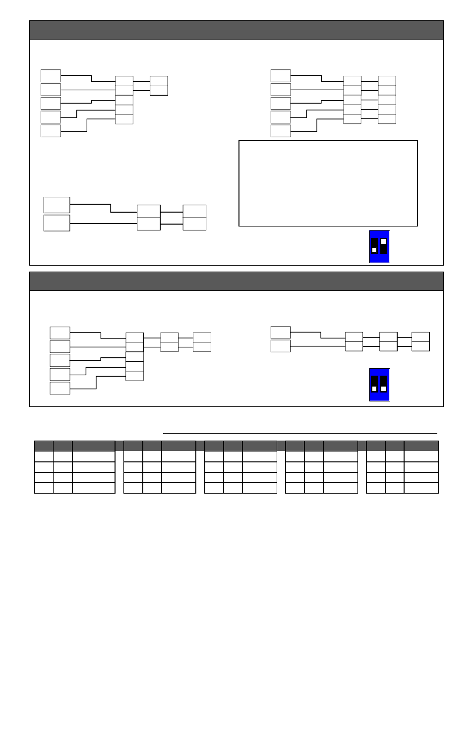
Wiring examples of 2 remote room sensors for averaging applications:
Wiring examples of 3 remote room sensors for averaging applications:
Temperature vs. resistance chart for 10 Kohm NTC thermistor
(R
25°C
=
10K
±3%, B
25/85°C
= 3975K±1.5%)
ºC
ºF
Kohm
ºC
ºF
Kohm ºC
ºF
Kohm ºC
ºF
Kohm ºC
ºF
Kohm
-40 -40 324.3197 -20
-4 94.5149
0 32 32.1910 20 68 12.4601 40 104 5.3467
-35 -31 234.4009 -15
5 71.2430
5 41 25.1119 25 77 10.0000 45 113 4.3881
-30 -22 171.3474 -10 14 54.1988 10 50 19.7390 30 86 8.0694 50 122 3.6202
-25 -13 126.6109
-5 23 41.5956 15 59 15.6286 35 95 6.5499 55 131 3.0016
C
ONFIGURING AND
S
TATUS
D
ISPLAY
I
NSTRUCTIONS
Status display
The Terminal Equipment Controller features a two-line, eight-character display. There is a
low level backlight level that is always active and can only be seen at night.
When left unattended, the Terminal Equipment Controller has an auto scrolling display
that shows the actual status of the system. There is an option in the configuration menu to
lockout the scrolling display and to only present the room temperature and conditional
outdoor temperature to the user. With this option enabled, no local status is given of mode,
occupancy and relative humidity.
Each item is scrolled one by one with the back lighting in low level mode. Pressing any
key will cause the back light to come on to high level. When left unattended for 10
Notes for averaging applications:
S3010W1000 and S3020W1000 can
be mixed matched.
S3010W1000 and S3020W1000 are
to be wired in parallel.
Respect the dip switch setting in
each remote sensor.
Dip switch
setting for:
2 sensors
S2-1 = OFF
S2-2 = ON
Dip switch
setting for:
3 sensors
S2-1 = OFF
S2-2 = OFF
1 x S3010W1000 and 1 x
S3020W1000
Remote wiring 2 sensors
S1=On,
S2=Off
Scom
RS
Scom
RS
VT7200 Series
BO 5
BI 2
RS
Scom
24 Vac
Com
Scom
RS
Scom
RS
C
DI
Aux
2 x
S3020W1000
Remote wiring 2 sensors
S2=On,
S3=Off
Scom
RS
Scom
RS
C
DI
Aux
VT7200 Series
BO 5
BI 2
RS
Scom
24 Vac
Com
Scom
RS
Scom
RS
C
DI
Aux
2 x S3010W1000
Remote wiring 2 sensors
S2=On,
S3=Off
Scom
RS
Scom
RS
VT7200 Series
RS
Scom
Scom
RS
Scom
RS
2x S3010W1000 and 1 x
S3020W1000
Remote wiring 3 sensors
S2=Off,
S3=Off
Scom
RS
Scom
RS
Scom
RS
Scom
RS
VT7200 Series
BO 5
BI 2
RS
Scom
24 Vac
Com
Scom
RS
Scom
RS
C
DI
Aux
3x S3010W1000
Remote wiring 3 sensors
S2=Off,
S3=Off
Scom
RS
Scom
RS
Scom
RS
Scom
RS
VT7200 Series
RS
Scom
Scom
RS
Scom
RS
1
2
O N
Dip switch
setting for:
2 sensors
S2-1 = OFF
S2-2 = ON
1
2
O N
Dip switch
setting for:
3 sensors
S2-1 = OFF
S2-2 = OFF