VACUUBRAND VHC Pro User Manual
Page 22
page 22 of 27
Documents are only to be used and distributed completely and unchanged. It is strictly the users´ responsibility to check carefully
the validity of this document with respect to his product. 25/11/2013 // 999281
+
Position any washers that are present between diaphragm
support disc and connection rod.
➨
Screw diaphragm clamping disc, diaphragm, diaphragm
support disc, and washers to connecting rod.
➨
Bring the diaphragm into a position in which it is in con-
tact with the housing and centered with respect to the bore
so that it will become clamped uniformly between housing
and head cover.
➨
Assemble head cover and valves.
+
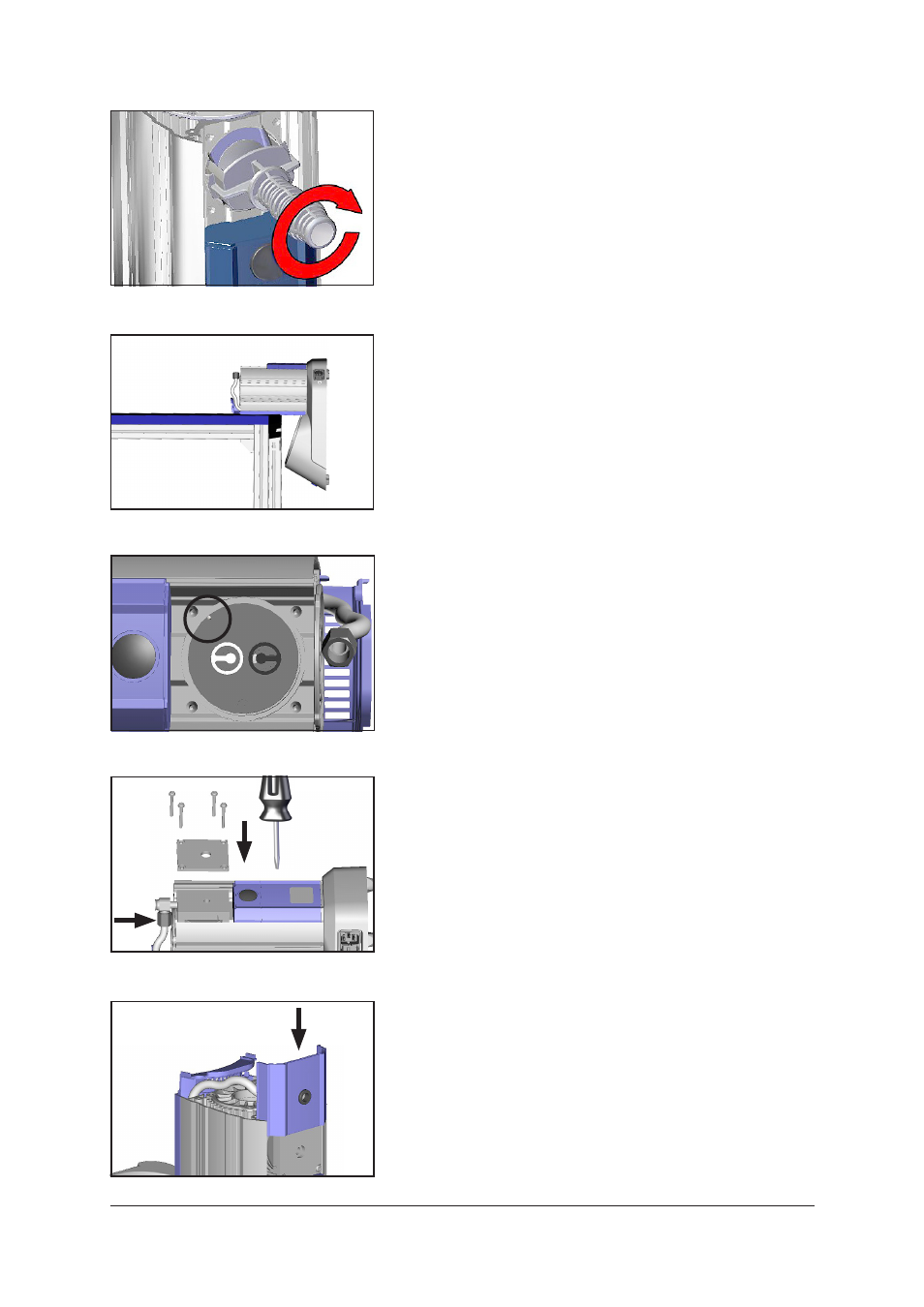
Pay attention to the correct position of the guidance pin in
the head cover (circle in figure)!
+
Pay attention to
correct orientation of the valves (see
figure):
Inlet side of pump head (black valve): The valve tongue
points at the kidney-shaped orifice in the valve seat.
Outlet side of pump head (white valve): The valve is ori-
ented the opposite direction as the valve at the inlet side.
Round orifice under the valve tongue.
➨
Lay down the BVC on the side of the pump, e. g., at the
edge of a workbench; support if necessary.
➨
Put on housing cover and housing cover insert.
+
Move housing cover insert slightly to ensure that the head
covers are correctly positioned.
➨
Pay attention to washers and position screws. Screw in
4 screws with washers at the housing cover diagonally,
loosely at first with a Torx driver T20, then tighten.
+
Do
not tighten until head cover is in contact with housing,
maximum torque: 2.2 ft
.
lb
f
(3 Nm).
➨
Position hose to elbow fitting and screw on the union nut.
➨
Position BVC upright.
➨
Assemble the cover so that the groove in the in the face
side of the cover is at the inlet of the pump.