Step 1 – install hood mount bars and filter stops, Step 2 – install filter channels and stiffeners, Step 3 – install filter rail assemblies – Twin City Hooded Propeller Roof Fans (Filtered Supply) - IM-4860FS User Manual
Page 2: Step 4 – install hood side rails, Step 5 – install end assy (male), Step 6 – install hood panels
2
Twin City IM-4860FS
Twin City IM-4860FS
3
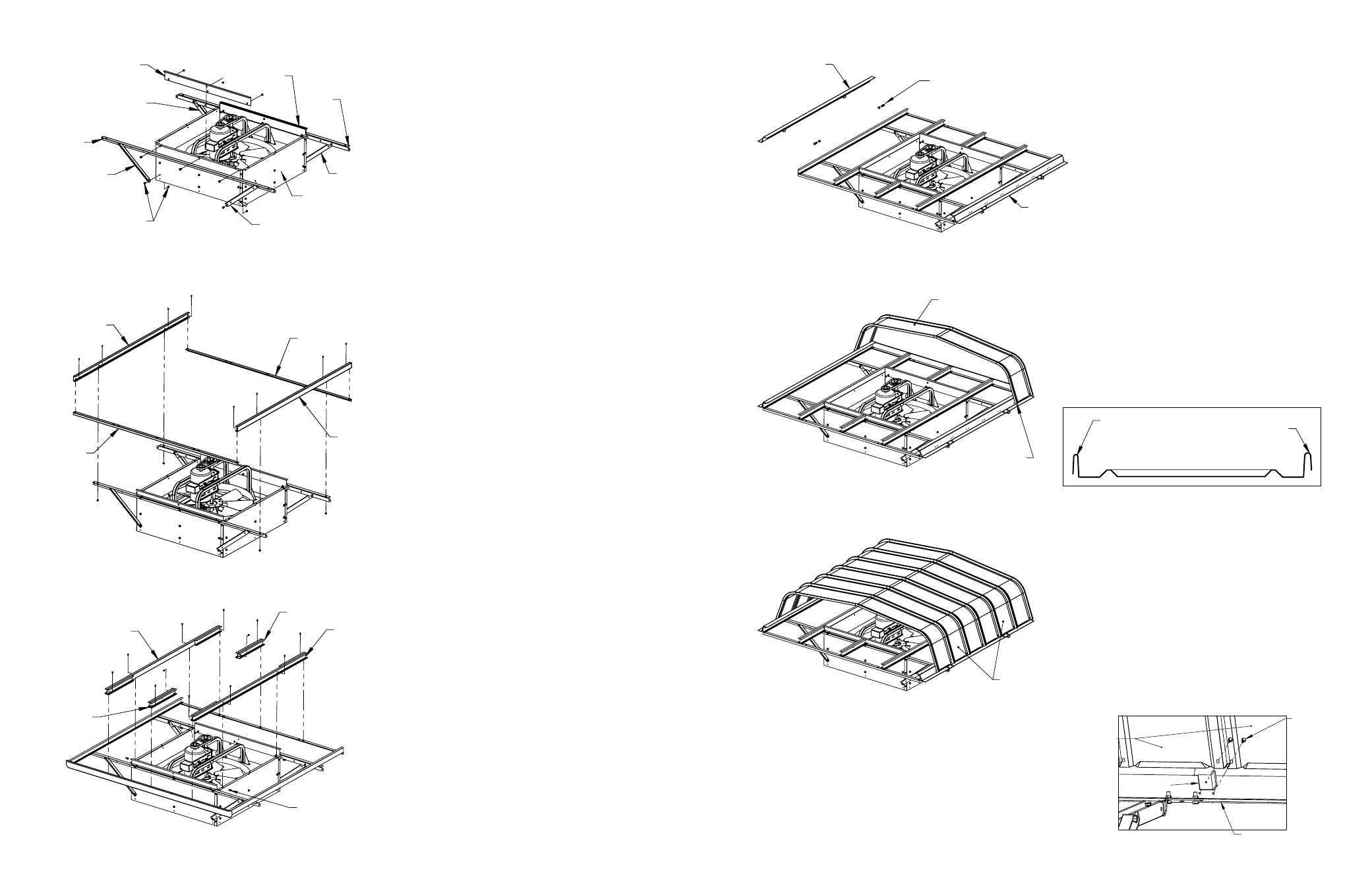
Step 1 – Install Hood Mount Bars
and Filter Stops
Fasteners (Kit #1):
Cap Screw, Serrated Flange, 3/8-16 x 0.75
Hex Nut, Serrated Flange, 3/8-16
A. Assemble Hood Mount Bars and Filter Stop
Plates on both sides of the fan housing,
using cap screws and nuts.
B. Assemble four Hood Gussets using cap
screws and nuts. The lower fasteners on the
gussets attach to the curb stop fasteners,
which are already installed on the fan hous-
ing. One at a time, remove the screws and
attach the gussets.
Hood
Hood
Mount
Bar
Hood
Gusset
Hood Gusset
Hood Gusset
Hood Gusset
Filter
Stop
Plate
Filter
Stop
Plate
Fasteners are
already installed
(four places)
Mount
Bar
Fan Housing
Side Panel
Step 2 – Install Filter Channels and
Stiffeners
Fasteners (Kit #7):
Cap Screw, Serrated Flange, 5/16-18 x 0.75
Hex Nut, Serrated Flange, 5/16-18
A. Assemble two Filter Channels to Hood Mount
Bars using cap screws and nuts.
B. Assemble two Stiffener Angles to the Filter
Channels using cap screws and nuts.
Step 3 – Install Filter Rail
Assemblies
Fasteners (Kit #7):
Cap Screw, Serrated Flange, 5/16-18 x 0.75
Hex Nut, Serrated Flange, 5/16-18
Nut Clip, 5/16-18
A. Install nut clips onto the fan Housing Side
Panel flanges as shown.
B. Assemble two Long Rail Assemblies using
cap screws and nuts.
C. Assemble two Short Rail Assemblies using
cap screws and nuts.
Filter
Channel
Stiffener
Angle
Stiffener
Angle
Filter
Channel
Long
Rail
Assembly
Short
Rail
Assembly
Short
Rail
Assembly
Long
Rail
Assembly
Nut Clips
End Panel Assembly
Male Type
Important - This
flange must
be male
Male Flange
(Narrow)
Female Flange
(Wide)
End View of Panel
Step 4 – Install Hood Side Rails
Fasteners (Kit #1):
Cap Screw, Serrated Flange, 3/8-16 x 1.25
Hex Nut, Serrated Flange, 3/8-16
A. Install two Hood Side Rail Assemblies to
the Hood Mount Bars using cap screws and
nuts. Do not fully tighten fasteners. They will
be tightened in Step 7.
Hood
Side Rail
Assembly
Hood
Side Rail
Assembly
3/8-16 x 1.25
Cap Screws
and Hex Nuts
Step 5 – Install End Assy (Male)
Fasteners (Kit #1):
Screws, #12
A. Assemble End Panel Assembly (male type)
using two #12 screws.
Step 6 – Install Hood Panels
Fasteners (Kit #1):
Screws, #12
A. Install the Hood Panels using #12 screws.
B. On Sizes 54 and 60, hood clips must be
installed at each interlocking rib while install-
ing the panels. Position the Hood Panel in
place and reach underneath to slide the clip
into place.
Hood Panels
End View of Panel
For Sizes 54 and 60,
install hood clips at each rib.
#12
Screws
Hood Side
Rail Assy
Hood
Panels
Hood Clip