For arrangements 3 & 7 – Twin City SWSI Nested Inlet Vanes - ES-394 User Manual
Page 2
2
TCF&B Engineering Supplement ES394
For Arrangements 3 & 7:
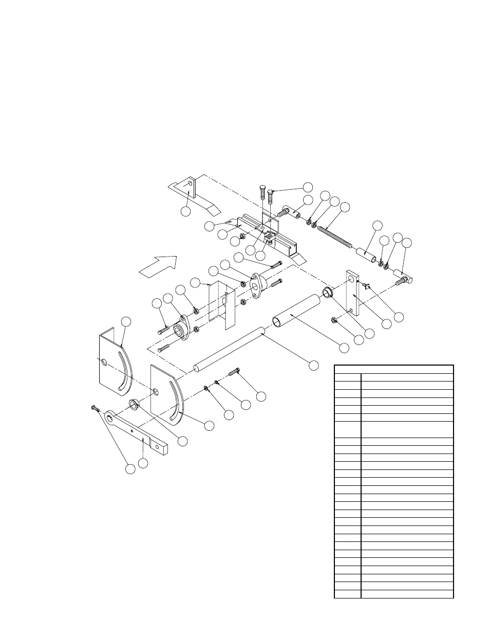
1. Using Figure 2 as a guide, assemble items 5 through
15 to the inlet vane. Threaded linkage rod (item 6)
may have to be cut to required length.
2. Center inlet vane in location of old vane or cone, and
rotate until inlet vane control ring is approximately in
the same position as shown in Figure 3. If old control
linkage is being reused, locate control ring clip so
that connecting link can be reattached.
3. For installation of new quadrant, using the dimensions
in Figure 4, position quadrant (item 2 or 2A) to the
housing side. Drill a hole in the fan housing side to
match outside diameter of control rod housing (item
4).
4. Weld quadrant (item 2 or 2A) to housing frame (or
housing side).
5. Reassemble bearing support frame and bolt it to the
fan housing as shown in Figure 5.
6. Reassemble bearing and tighten bearing fasteners
7. Remove blocking under wheel and check to be sure
wheel turns freely. Adjust bearing position or inlet
vane position as required.
8. Assemble the remaining parts of control system
according to Figure 2. Adjust position of connecting
links as required to allow the vane to open and close
smoothly.
9. Weld threaded linkage housing to hex nuts (item 12).
Spot weld the control rod to vane handle and control
linkage bar.
AIRFLOW
17
16
18
19
16
17
26
13
25
24
10
11
12
6
7
12
23
5
15
14
4
3
20
21
22
2
15
1
27
11
10
9
8
8A
2A
18
Figure 2. Nested Inlet Vane Control System for SWSI BC, BAF, BCS Fans
ITEM
DESCRIPTION
01
VANE HANDLE
02
QUADRANT
03
CONTROL ROD
04
CONTROL ROD HOUSING
05
CONTROL LINKAGE BAR
06
CONTROL LINKAGE ROD
07
THREADED LINKAGE ROD
HSG.
08
CONTROL RING CLIP
09
CONTROL RING
10
BALL JOINT
11
HEX NUT
12
HEX NUT
13
HEX NUT
14
HEX NUT
15
OILITE BEARING
16
FLANGE BEARING
17
HEX BOLT
18
NEX NUT
19
BEARING BRACKET
20
HEX HEAD SCREW
21
SPRING LOCK WASHER
22
FLAT WASHER
23
SQUARE HEAD SETSCREW
24
HEX HEAD SCREW
25
UNISTRUT
26
UNISTRUT CLAMPING NUT
27
SQUARE HEAD SETSCREW
NOTES:
1. Items 16, 17, 18, 19 used for 1.5" and larger dia. control rod.
2. Items 4, 15 used for .75" to 1.25" dia. control rod.
3. Items 24, 25, 26 used for fan sizes 245–890.
4. Item 2A used for rotatable housing design.
5. Item 8A used for fan sizes 165–222.
6. Item 19, bearing bracket, shall be welded to inside of the fan housing.
7. Item 2, quandrant for nonrotatable fan, shall be welded on fan housing frame.
8. Item 2A, quadrant for rotatable fan, shal be welded on fan housing.
9. Measure threaded linkage rod length to fit.