Top Flite TOPA1025 User Manual
Page 5
5
ASSEMBLE THE WING
❏
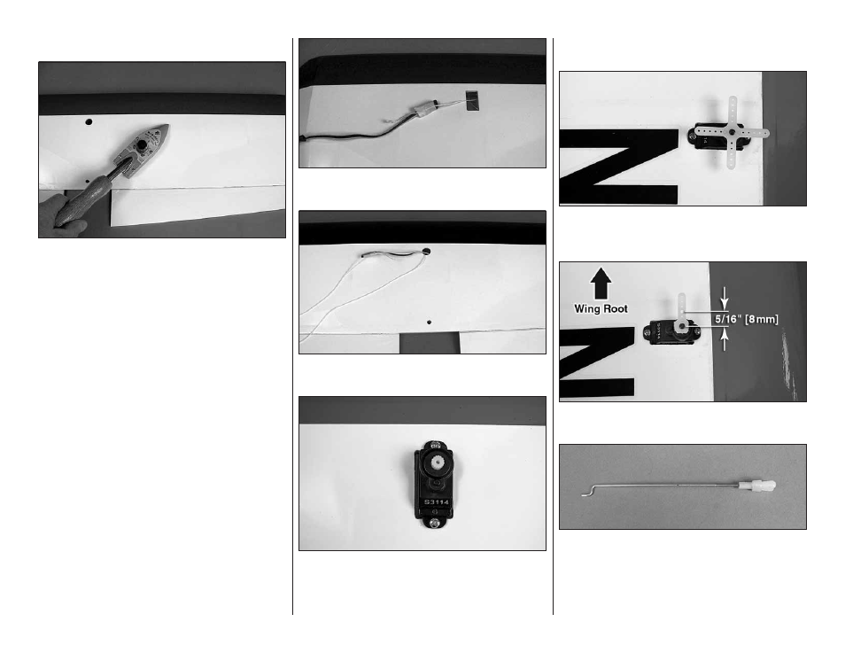
1. If necessary, use a covering iron with a covering
sock to go over the wing and aileron to remove any
wrinkles. The best method to remove the wrinkles is
to glide the iron over the covering until the wrinkles
disappear, then go over the area again, pushing down
on the iron to bond the covering to the wood. If the
wrinkles don’t disappear, the balsa in that area might
be fl exing inward. If this is happening, don’t press down.
Simply let the heat of the iron shrink the covering. If
the wrinkles momentarily disappear, then immediately
reappear, the iron may be too hot, thus causing air
bubbles. Lower the temperature of the iron or use a
sharp #11 blade or T-pin to puncture several holes in the
covering, then reheat. The suggested iron temperature
is around 360 degrees F.
MOUNT THE AILERON SERVOS
❏
❏
1. Connect a 6" [152mm] servo extension to
one of the aileron servos. Secure the extension to
the servo lead with a piece of heat shrink or electrical
tape (not included).
❏
❏
2. Carefully pull the string from the aileron servo
opening and tie it to the end of the servo extension.
❏
❏
3. Pull the aileron servo lead through the wing
and out of the opening on the top of the wing.
❏
❏
4. Use a #55 drill bit or small T-pin to drill pilot
holes for the servo mounting screws. Mount the aileron
in the wing with two #2 x 1/4" [2 x 6mm] sheet metal
screws. Remove the screws and servo. Apply a drop
of thin CA in each screw hole. After the CA has cured,
reinstall the aileron servo and screws.
❏
❏
5. Install a servo arm on the aileron servo so
that it is perpendicular to the centerline of the servo.
Remove the three unused arms.
❏
❏
6. Use a 1/16" [1.6mm] drill bit to enlarge the
hole 5/16" [8mm] from the center of the servo arm.
❏
❏
7. Thread a nylon clevis 20 turns onto the 2-56 x
4-7/16" [110mm] metal pushrod. Slide a silicone clevis
keeper over the nylon clevis.
❏
❏
8. Connect the nylon clevis in the enlarged hole
of the servo arm.