Get the model ready to fly – Top Flite TOPA1025 User Manual
Page 10
10
❏
4. Carefully balance the propeller and any spare
propellers. An unbalanced propeller can be the single
most signifi cant cause of vibration that can damage
the model. Not only will motor mounting screws loosen,
possibly with disastrous effect, but vibration may also
damage the receiver.
We use a Top Flite Precision Magnetic Prop Balancer
(TOPQ5700) in the workshop and keep a Great Planes
Fingertip Prop Balancer (GPMQ5000) in our fl ight box.
❏
5. Install the spinner and propeller. Secure the
spinner cone to the backplate with two 2.5 x 10mm
sheet metal screws.
APPLY THE DECALS
❏
1. The decals are die-cut from the factory.
❏
2. Be certain the model is clean and free from oily
fi ngerprints and dust. Prepare a dishpan or small
bucket with a mixture of liquid dish soap and warm
water—about 1/2 teaspoon of soap per gallon of water.
Submerse one of the decals in the solution and peel
off the paper backing. Note: Even though the decals
have a “sticky-back” and are not the water transfer type,
submersing them in soap & water allows accurate
positioning and reduces air bubbles underneath.
❏
3. Position decal on the model where desired.
Holding the decal down, use a paper towel to wipe
most of the water away.
❏
4. Use a piece of soft balsa or something similar to
squeegee remaining water from under the decal. Apply
the rest of the decals the same way.
❏
5. The recommended pilot will require some trimming
to fi t in the cowl. We used a piece of scrap wood to
make a base on which to mount the pilot.
GET THE MODEL READY TO FLY
BALANCE THE MODEL LATERALLY
❏
1. With the wing level, have an assistant help you
lift the model by the spinner and the bottom of the fuse
under the TE of the fi n. Do this several times.
❏
2. If one wing always drops when you lift the model,
it means that side is heavy. Balance the airplane by
adding weight to the other wing tip. An airplane that
has been laterally balanced will track better in
loops and other maneuvers.
CHECK THE CONTROL DIRECTIONS
❏
1. Switch on the transmitter and receiver and center
the trims. If necessary, remove the servo arms from
the servos and reposition them so they are centered.
Reinstall the screws that hold on the servo arms.
❏
2. With the transmitter and receiver still on, check
all the control surfaces to see if they are centered. If
necessary, adjust the clevises on the aileron pushrods
and the wheel collars on the elevator and rudder
pushrods to center the control surfaces.
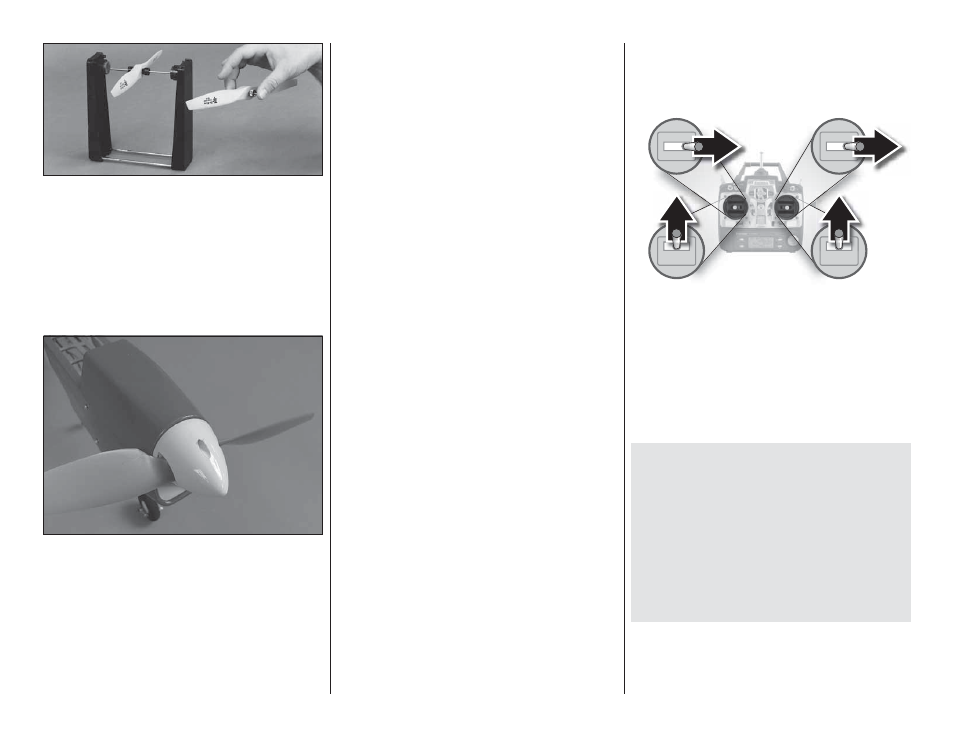
FULL
THROTTLE
RUDDER
MOVES
RIGHT
ELEVATOR
MOVES DOWN
RIGHT AILERON
MOVES UP
LEFT AILERON
MOVES DOWN
4-CHANNEL RADIO SETUP
(STANDARD MODE 2)
❏
3. Make certain that the control surfaces respond
in the correct direction as shown in the diagram. If any
of the controls respond in the wrong direction, use the
servo reversing in the transmitter to reverse the servos
connected to those controls. Be certain the control
surfaces have remained centered. Adjust if necessary.
SET THE CONTROL THROWS
To ensure a successful fi rst fl ight, set up your Mini
Contender EP ARF according to the control throws
specifi ed in this manual. The throws have been
determined through actual fl ight testing and accurate
record-keeping, allowing the model to perform in the
manner in which it was intended. If, after you have
become accustomed to the way the Mini Contender
EP ARF fl ies, you would like to change the throws
to suit your taste, that is fi ne. However, too much
control throw could make the model too responsive
and diffi cult to control, so remember, “more is not
always better.”