Top Flite TOPA1025 User Manual
Page 11
11
❏
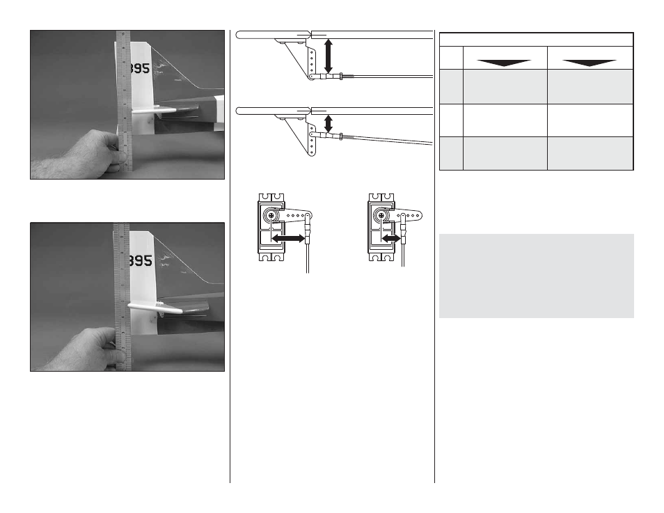
1. Hold a ruler vertically on your workbench against
the widest part (front to back) of the trailing edge of the
elevator. Note the measurement on the ruler.
❏
2. Measure the high rate elevator throw fi rst. Move
the elevator up with your transmitter and move the
ruler forward so it will remain contacting the trailing
edge. The distance the elevator moves up from center
is the “up” elevator throw. Measure the down elevator
throw the same way.
Pushrod Farther Out
Pushrod Farther Out
LESS
THROW
Pushrod Closer In
MORE
THROW
MORE
THROW
Pushrod Closer In
LESS
THROW
❏
3. If necessary, adjust the location of the pushrod
on the servo arm or on the elevator horn, or program
the ATVs in your transmitter to increase or decrease
the throw according to the measurements in the control
throws chart.
❏
4. Measure and set the low rate elevator throws
and the high and low rate throws for the rest of the
control surfaces the same way.
If your radio does not have dual rates, we recommend
setting the throws at the high rate settings.
NOTE: The throws are measured at the widest part
of the elevators, rudder and ailerons.
These are the recommended control surface throws:
ELEV
A
TOR
HIGH RATE
LOW RATE
Up and
Down
3/8"
[10 mm]
11°
Up and
Down
1/4"
[ 6 mm]
7°
Up and
Down
5/8"
[16 mm]
25°
Up and
Down
3/8"
[10 mm]
14°
Right
& Left
1-1/8"
[29mm]
22°
Right
& Left
3/4"
[19 mm]
14°
RUDDER
AILERONS
Note: The high rate ailerons can be sensitive around
center. We recommend that 20% to 30% expo on the
high rate ailerons.
BALANCE THE MODEL (C.G.)
More than any other factor, the C.G. (center of gravity/
balance point) can have the greatest effect on how
a model fl ies and could determine whether or not
your fi rst fl ight will be successful. If you value your
model and wish to enjoy it for many fl ights, DO NOT
OVERLOOK THIS IMPORTANT PROCEDURE. A
model that is not properly balanced may be unstable
and possibly unfl yable.
At this stage the model should be in ready-to-fl y
condition with all of the components in place including
the complete radio system, motor battery, propeller,
spinner and canopy.