Top Flite TOPA1000 User Manual
Page 7
❏
3.
P
osition the stab on the fuselage and align it as
bef
ore
.
F
rom the rear of the model, chec
k that the
stab is par
allel with the wing.
If it is not, lightly sand
the stab mount on the fuselage as needed.
When
y
ou are satisfied with the alignment, glue the stab in
place with medium CA or epo
xy
.
❏
4.
Inser
t the f
our CA hinges in the precut slots in
the ele
v
ator
.T
rial fit the ele
v
ator to the stab
.M
ak
e an
y
adjustments needed to the hinge slots
.
When
satisfied with the fit, glue the hinges in place with
three drops of thin CA on the top and bottom of the
hinges
.
DO NO
T use an
y CA acceler
ator
.
❏
5.
Mount the 90-deg
ree metal br
ac
ke
t to the fuselage
left side using a large w
ood scre
w
.There is a pilot hole
already dr
illed in the fuselage at the correct location.
Be
sure to inser
t the ele
vator pushrod into the br
ac
ke
t
bef
ore y
ou mount it into position.
❏
6.
The n
y
lon control hor
n is mounted to the bottom of
the ele
vator inline with the pushrod.
Mar
k the location
of the mounting holes and dr
ill 3/32”
[2.4mm] holes
.
Mount the control hor
n using the supplied 2-56 x 1/2”
[12.7mm] machine scre
ws and n
ylon bac
kplate
.
❏
7.
Enlarge the holes in the control hor
n with a
3/32”
[2.4mm] dr
ill bit.
Inser
t the ele
v
ator pushrod
into the second hole from the end.
Use a plastic
retainer to hold the pushrod in place
.
Install the
V
e
rtical Fin
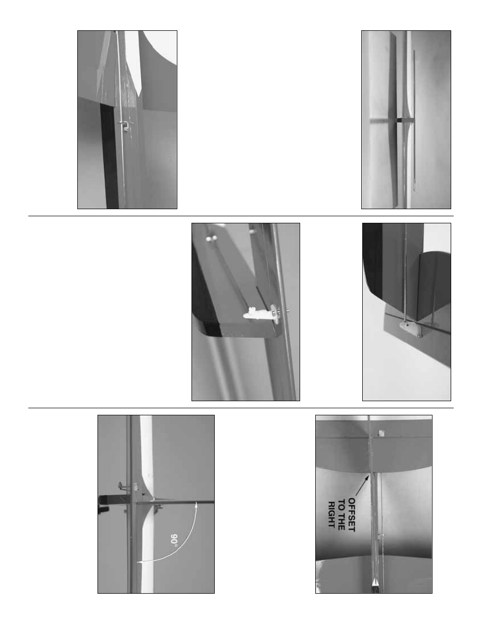
❏
1.
P
osition the v
e
rtical fin on the fuselage and
hor
iz
ontal stab
.
Note that the leading edge of the fin
is centered on the fuselage just aft of the canop
y,
b
u
t
the rear of the fin is off center to the r
ight.
This will
help increase the flying line tension.
Mar
k the outline
of the fin on the fuselage and stab
.
❏
2.
T
rim the co
v
e
ring from the fuselage and stab
inside the lines
.
R
emo
v
e an
y f
e
lt-tip pen mar
ks
.
Glue
the v
e
rtical fin in place with epo
xy
.
Be sure the fin is
per
pendicular to the hor
iz
ontal stab
.
After the epo
xy
hardens
, reinf
orce the joint as needed.
- 7
-