Dimensional diagram – Toa PJ-154BS User Manual
Page 4
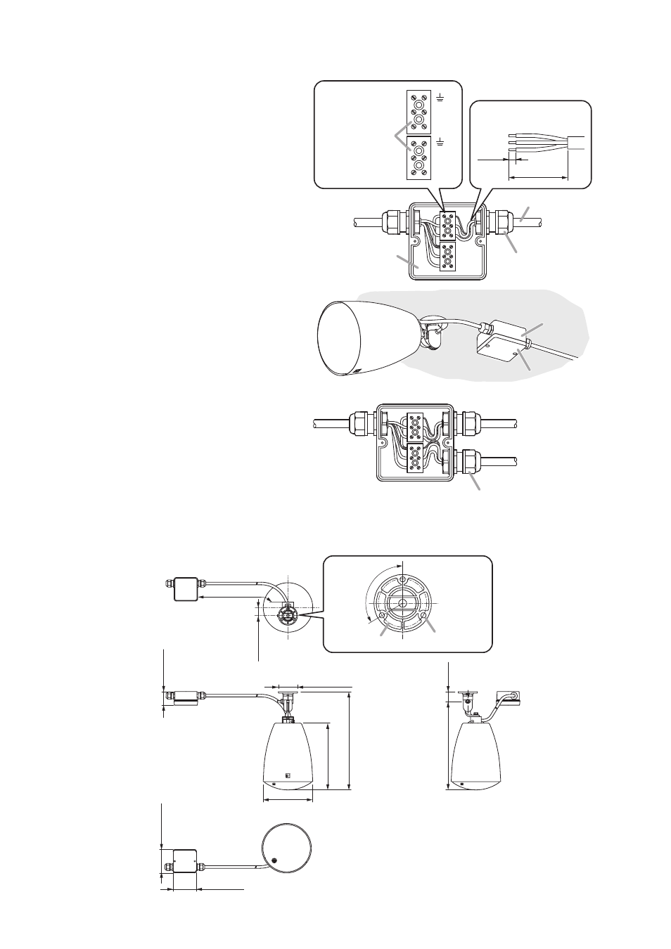
Terminal box
3
-2
Cable gland
To speaker
COM
HOT
COM
HOT
Terminal blocks
3
-3
[Cable end treatment]
55 mm (2.17")
8 mm
(0.31")
3
-1
From amplifier
Amplifier cable
Step 3. Connect the amplifier cable (cable from amplifier) to the terminal block in the terminal box.
In advance of the cable connection, remove 2 screws fixing the terminal box’s cover plate to detach it.
3-1. Strip the amplifier cable jacket as
shown at right.
3-2. Run the amplifier cable through the
cable gland.
3-3. Connect the amplifier cable according
to the polarity indication at the terminal
block.
3-4. Secure the terminal box to the ceiling
or wall with screws using the 2
mounting screw knockouts in the
terminal box. Then, secure the
detached terminal box’s cover plate
with screws.
Note
Screws for mounting the terminal box
to the ceiling or wall are not supplied.
Use screws that are appropriate for
the ceiling's or wall's material and
structure.
Approx.
625 (24.61)
51 (2.01)
88 (3.46)
88 (3.46)
ш186
(ш7.32)
251 (9.88)
369 (14.53)
ш72 (ш2.83)
333 (13.11)
36
(1.42)
[Top]
[Front]
[Side]
[Bottom]
30.5 (1.2)
120º
ш60 (ш2.36)
3-ш6.5 (ш0.26)
5. DIMENSIONAL DIAGRAM
Unit: mm (in)
4
[When making a bridge connection]
Punch out the knockout in the terminal box,
attach the cable gland (option) there, then make
cable connections to the next speakers in the
same way as described in Steps 3-1 through 3-3.
Terminal box
Ceiling
3
-4
To the next speaker
Optional part