Installation, Wiring diagrams, General description – Toa PC-658R User Manual
Page 2
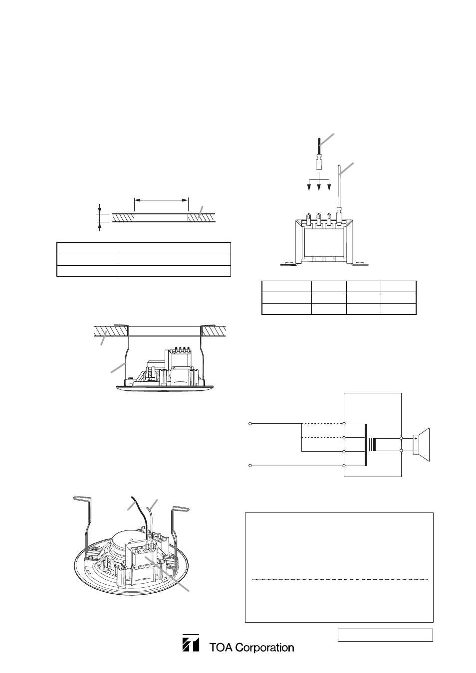
3-2. Change the input impedance as needed.
The speaker's input is factory-preset to 1.7
kΩ.
When changing the input impedance, detach
the black wire connected to the matching
transformer, and reinsert it into the desired
input tap referring to the table below.
Step 4. Push the panel surface into the mounting
hole.
4. INSTALLATION
Step 1. Using the supplied paper pattern as a guide,
open a mounting hole of the dimension
specified below in the ceiling.
5. WIRING DIAGRAMS
Step 2. Hook the speaker mounting spring into the
mounting hole in the ceiling.
Step 3. Make wiring.
3-1. Connect the speaker cable (from the
amplifier) referring to the figure below.
Connect its HOT line to the black lead wire,
and COM line to the white one.
8 Ω
10 kΩ
3.3 kΩ
1.7 kΩ*
* Factory-preset
0
COM (white)
HOT (black)
Matching
transformer
COM
3. GENERAL DESCRIPTION
Integrated with a resin panel and speaker frame, the
PC-648R and PC-658R are the ceiling mount
speakers with a metal grille attached.
They feature spring clamp mechanism for easy
speaker mounting to the ceiling.
The input impedance can be easily changed by
changing the tap position of the transformer.
533-06-162-4B
URL: http://www.toa.jp/
Traceability Information for Europe
(EMC directive 2004/108/EC)
Manufacturer:
TOA Corporation
7-2-1, Minatojima Nakamachi, Chuo-ku, Kobe, Hyogo,
Japan
Authorized representative:
TOA Electronics Europe GmbH
Suederstrasse 282, 20537 Hamburg,
Germany
Ceiling
5 – 25 mm
(0.2” – 0.98”)
øA
Model No.
øA
PC-648R
ø145 ±5 mm (ø5.71" ±0.2")
PC-658R
ø170 ±5 mm (ø6.69" ±0.2")
Ceiling
Speaker mounting
spring
The figure shows PC-648R.
The figure shows PC-648R.
Matching
transformer
COM (White)
HOT (Black)
3.3 kΩ
10
kΩ
1.7 kΩ
HOT (Black)
COM (White)
Impedance 1.7
kΩ
3.3 kΩ
10 kΩ
100 V line
6 W
3 W
1 W
70 V line
3 W
1.5 W
0.5 W