Installation, Specifications – Toa PC-3CL User Manual
Page 2
INSTALLATION
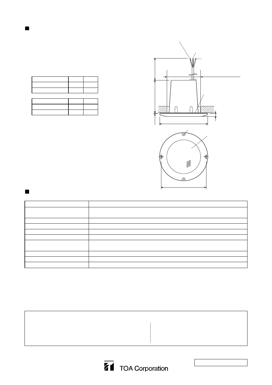
1. Make a 100 mm diameter hole in a ceiling. (It is possible
to use the supplied pattern paper for a 100 mm diameter
hole.)
2. Attach the supplied gasket to the panel.
3. Connect the input cable to the speaker cable.
4. Using the four supplied speaker mounting screws (4x15),
secure the speaker to the ceiling.
Caution: Ensure that the ceiling surface is strong
(equivalent to the plywood thicker than 5 mm)
enough to hold the screws.
70 V Line
COM
HOT
1.5 W connection
White
Red
0.5 W connection
White
Black
100 V Line
COM
HOT
3 W connection
White
Red
1 W connection
White
Black
ø100 mm
(mounting hole diameter)
White (COM)
Red
(100 V Line: 3 W, 70 V Line: 1.5 W)
Black
(100 V Line: 1 W, 70 V Line: 0.5 W)
Gasket
ø139 mm
Punched grille
2 mm
94.5 mm
330 mm
4-ø4.5 mm
ø130 mm
SPECIFICATIONS
Rated Input
3 W
Rated Impedance
3.3 kΩ (100 V Line: 3 W, 70 V Line: 1.5 W)
10 kΩ (100 V Line: 1 W, 70 V Line: 0.5 W)
Output Sound Pressure Level
87 dB (1 W, 1 m)
Frequency Response
150 – 20,000 Hz
Operating Temperature Range
-20°C to +60°C
Dust/Water Protection
IP64
Finish
Frame: ABS resin, chrome plating
Punched grille: Stainless steel
Mounting hole diameter
100 mm
Dimensions
ø 139 x 104.5 (d) mm
Weight 550
g
8 mm
Note : The design and specifications are subject to change without notice for improvement.
• Accessories
Gasket (silicon rubber) ...................... 1
Speaker mounting screw .................. 4
Pattern paper (ø100 mm hole) .......... 1
333-01-039-2C
URL: http://www.toa.jp/
Traceability Information for Europe
Manufacturer:
TOA Corporation
7-2-1, Minatojima-Nakamachi, Chuo-ku, Kobe, Hyogo,
Japan
Authorized representative:
TOA Electronics Europe GmbH
Suederstrasse 282, 20537 Hamburg,
Germany