Installation – Toa PC-1869S User Manual
Page 2
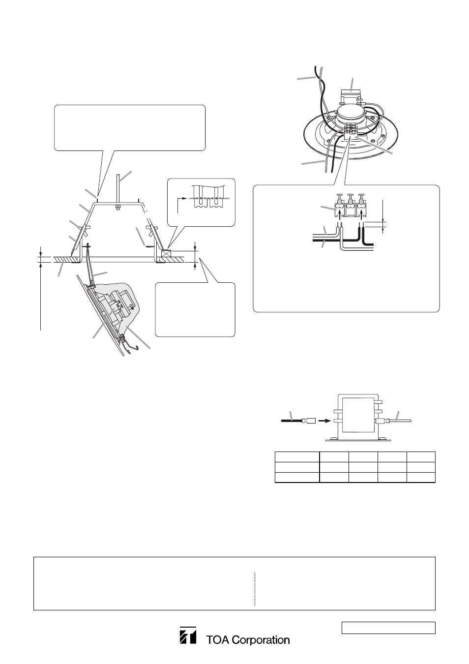
4-2. Change the input impedance as needed.
The speaker's input is factory-preset to 1.7 kΩ.
When changing the input impedance, detach the
black wire connected to the matching transformer,
and reinsert it into the desired input tap referring to
the table below.
Step 5. Hook another speaker spring in another catcher.
Then, press the speaker assembly into the
mounting bracket. Force of the springs will keep
the speaker in place.
5. INSTALLATION
Step 1. Make a 150 ±3 mm (5.91 ±0.12 in) diameter hole in
the ceiling. Marking-off pins provided on the
mounting bracket will help draw the circle of its
diameter on the ceiling.
Step 2. Place the mounting bracket in the hole and secure
it with the thumb screws in the two ceiling clamps.
Note
A suspension bolt may be used instead for fixing
the mounting bracket.
Step 3. Hook one speaker spring (V-shaped spring) in the
spring catcher of the bracket.
Step 4. Make wiring.
4-1. Insert the lead-in cables (cables from the amplifier)
and lead-out cables (cables to other speakers) into
the input connector.
(Continued to the top right)
533-06-185-70
URL: http://www.toa.jp/
Traceability Information for Europe (EMC directive 2004/108/EC)
Manufacturer:
TOA Corporation
7-2-1, Minatojima Nakamachi, Chuo-ku, Kobe, Hyogo,
Japan
Authorized representative:
TOA Electronics Europe GmbH
Suederstrasse 282, 20537 Hamburg,
Germany
Input connector
Matching transformer
Speaker cable
(From the amplifier)
Speaker cable
(To the next speaker)
Input connector
From the amplifier
To the next speaker
COM (–)
HOT (+)
9 mm
(0.35”)
Applicable cable
Solid wire: ш0.8 – ш1.6 mm
(equivalent to AWG 20 – 14)
Stranded wire (7-core): 0.75 – 1.25 mm
2
(equivalent to AWG 18 – 16)
View with dust cover removed.
[When making a bridge connection]
3.3kΩ
1.7kΩ
COM
6.7kΩ
13kΩ
Matching transformer
HOT (Black)
COM (White)
Impedance
1.7 kΩ
3.3 kΩ
6.7 kΩ
13 kΩ
100 V line
6 W
3 W
1.5 W
0.8 W
70 V line
3 W
1.5 W
0.8 W
0.4 W
Input connector
1
2
3
Ceiling
Speaker spring
Marking-off pin
Suspension bolt
Spring catcher
34 mm (1.34”) max.
Cloth dust cover
(with the input connector exposed)
Bent position
Mounting bracket
Thumb screw
Ceiling clamp
Note
Raise both pins, and draw a circle with the
sharp pin as its center and another pin as a
scriber.
Note
Max. 50 mm (1.97")
allowable with the
ceiling clamp bent
as designated above.