Mounting the speaker on the wall – Toa T-650 User Manual
Page 3
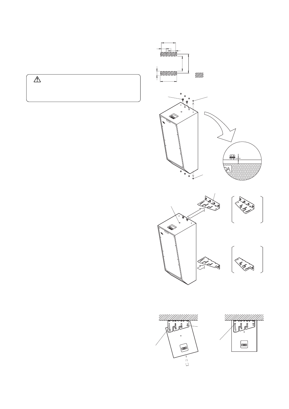
MOUNTING THE SPEAKER ON THE WALL
207
240
69 69
60
827
887
Wall mounting dimension
represents the surface to
which the bracket attaches.
1. Attach Speaker Brackets A and B to the upper and lower
parts of the wall using a total of eight bolts (four each per
bracket). (Note that the mounting position of Bracket A
or B differs depending on the direction in which the
speaker is inclined. Refer to the figures shown at the
lower right.)
Note
Bolts for attaching the brackets are not supplied with the
unit. Use appropriate types depending on the material and
construction of the wall.
2. Remove caps filling in eight screw holes in the unit's top
and bottom panels. Insert two of the eight supplied
speaker mounting bolts into two central holes in the top
panel, then tighten the bolts so that their heads stick out
5-6 mm, as shown in the figure at right.
Note
Take care that the speaker mounting bolt does not stick out
extremely.
3. Fit the mounted bolts into the two slots in the upper
bracket.
Memo
• Use the cable entry hole when the speaker cable needs
be left pulled out.
• It is also possible to lift up the speaker by means of an
eyebolt when installing it.
4. Fully inserting the bolts beyond the branch of the slot
temporarily secures the unit.
5. Insert the speaker mounting bolts into the remaining two
screw holes in the top panel. Use an oval hole for direct
speaker attachment located in the back of the bracket
when fitting the speaker's rear panel closely to the wall.
Use the angle adjustment slot and axial hole located in
the front of the bracket when adjusting angles.
6. Determine a horizontal installation angle, then tighten all
of the four speaker mounting bolts. (Note that if the
speaker's back is fitted closely to the wall, you cannot
change the installation angle.)
7. Similarly, secure the lower mounting bracket to the
speaker's bottom surface using four speaker mounting
bolts.
* Bracket arrangement when inclining the speaker to the
right.
** Bracket arrangement when inclining the speaker to the
left.
WARNING
Check to ensure that the mounting surface is strong
enough to stand the weight of a load before
beginning installation.
Speaker
mounting bolt
Cap
5 – 6 mm
Cap
Mounting
bracket A *
Mounting
bracket A **
Mounting
bracket B
Mounting
bracket B
15
°
Axial hole
Oval hole for
direct speaker
attachment
Angle
adjustment
slot
Inclined speaker installation
(Maximum 15
°)
Direct speaker attachment