Single-amplifier drive and bi-amplifier drive, Internal wiring diagram, Single-amplifier drive – Toa SR-PP4 User Manual
Page 8: Bi-amplifier drive
8
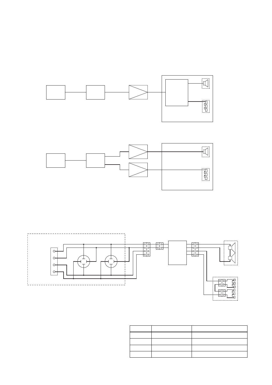
6. SINGLE-AMPLIFIER DRIVE AND BI-AMPLIFIER DRIVE
The SR-S4 series speakers are factory-preset to be driven by a single amplifier, however this setting can be
changed to a bi-amplifier drive system by changing the speaker's internal wiring.
(See p. 12; Changing Single-Amplifier Drive to Bi-Amplifier Drive System.)
• Single-amplifier drive
Note: Use a digital processor as required.
• Bi-amplifier drive
Mixer/preamplifier
Digital processor
Power amplifier
Passive
network
SR-S4L/S4S
LOW
HIGH
Tweeters
Woofers
x
8
x
8
Mixer/preamplifier
Digital processor
Power amplifier
Tweeters
Woofers
SR-S4L/S4S
LOW
HIGH
LOW
HIGH
x
8
x
8
7. INTERNAL WIRING DIAGRAM
When shipped from the factory, the speaker is internally connected as shown below.
• Since the Neutrik NL4MP connectors and screw terminals are internally connected in parallel, either one can
be used for connection.
• The Neutrik NL4MP connector's pins are wired
as shown at right.
The connector (connection cable side) suited to
the Neutrik NL4MP is the Neutrik NL4FC.
Screw terminals
Neutrik NL4MP connectors
Input terminal panel
INPUT +
INPUT –
THROUGH
THROUGH
2+
1+
2–
1–
2+
1+
2–
1–
x 4
x 4
Passive
network
Tweeters
Woofers
Pin No.
SR-S4L, SR-S4S
Screw terminal indication
1 +
Speaker +
INPUT +
1 –
Speaker –
INPUT –
2 +
–
THROUGH
2 –
–
THROUGH