Toa PC-1867FC User Manual
Page 3
Secure channel bar or
suspension bracket
Snap ring
Safety wire
(prepared separately)
Rubber grommet
Dome mounting
bracket
Terminal fitting
metal
Fire dome
Ceiling
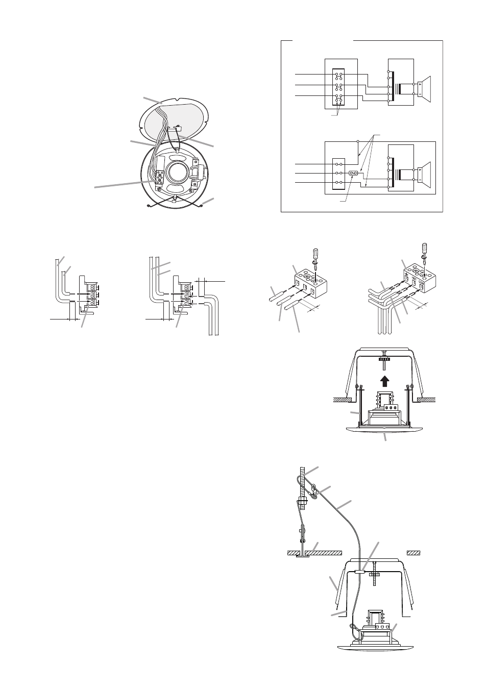
Step 8. Connect the speaker cable.
Wire the speaker according to the terminal indication.
Note: Hook the two ends of one of the speaker
mounting springs into the hooks in the fire
dome during connection.
Fire dome mounted
to the ceiling
Terminal block
• PC-1867F:
• PC-1867FC:
Push-in terminal
Screw terminal
Speaker mounting
spring
Speaker mounting
spring
PC-1867FC shown.
Speaker cable
Step 9. Hook the remaining speaker mounting spring into its
corresponding hook in the dome, then push the
speaker up into the fire dome.
Caution
Do not press directly on the front grille, as the grille
could become dented or damaged.
Note
See to it that the speaker cable is not pinched between
the fire dome and the front grille.
Speaker mounting
spring
Front grille
13 k
Ω
8
Ω
0
6.7 k
Ω
3.3 k
Ω
3 W (3.3 k
Ω)
6 W (1.7 k
Ω)
COM
BRN
WHT
BLK
1.7 k
Ω
COM
Terminal
(Factory-preset transformer connection)
13 k
Ω
6.7 k
Ω
3.3 k
Ω
Earth
6 W (1.7 k
Ω)
COM
Thermal fuse (72
°C)
(Factory-preset transformer connection)
Incombustible cable
Steatite
Terminal
1.7 k
Ω
COM
8
Ω
0
• PC-1867F
• PC-1867FC
Bridging terminal
Wiring diagram
[PC-1867F terminal block (1.7 k
Ω use)]
• When no bridge connection
is made
• When making a bridge
connection
[PC-1867FC terminal block (1.7 k
Ω use)]
• When no bridge connection
is made
• When making a bridge
connection
9 mm
COM
6 W (1.7 k
Ω)
9 mm
9 mm
COM
Push-in terminal
Push-in terminal
6 W (1.7 k
Ω)
From Amplifier
To the next speaker
From
Amplifier
To the next speaker
COM
COM
Earth
Earth
Screw terminal
Screw terminal
6 W (1.7 k
Ω)
6 W (1.7 k
Ω)
5 mm
5 mm
4. INSTALLING THE SAFETY WIRE (prepared separately by the installer)
Step 1. Tie one end of the safety wire around the terminal fitting
metal.
Note: When using a bare safety wire, wrap insulation
tape around it to prevent electrical contact with
the connection terminals, transformer taps, or
other electric parts.
Step 2. Make a cut in the rubber grommet with a knife or a
screwdriver, then run the safety wire through it.
Step 3. Tie snap ring around a secure channel bar or
suspension bracket.
Step 4. Feed the speaker cable through the rubber grommet
into the dome interior.
Step 5. Secure the fire dome assembly in the ceiling, then
connect the speaker cable to the terminal block.
Step 6. Attach the speaker to the fire dome.
Note: If the speaker cable and safety wire are too long,
to prevent them from being tangled inside the fire
dome, gently push them back out of the fire dome
so the rubber grommet does not get removed.