V.35 – Cabletron Systems CSX200 User Manual
Page 61
WPIM-SY
CSX200 Installation Guide
A-5
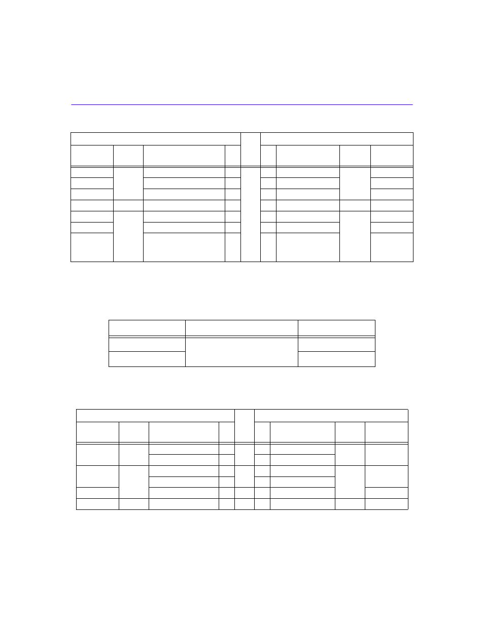
V.35
shows the connector number, cable assembly description, and connector type.
provides pin assignments for the V.35 interface cable.
CE
DTE
Ring Indicator
22
15
Incoming Call
DTE
IC
TM
Test Mode
25
18
Test Mode
TM
CC
DCE Ready
6
11
Data Mode
DM
CD
DCE
DTE Ready
20
12
Terminal Ready
DCE
TR
SHIELD
1
AC
Signal Common
23
20
Receive Common
RC
AB
Signal Common
7
19
30
37
Send Common
Terminal Ready B
Signal Ground
SG
TR_B
SC
Table A-8
V.35 Interface
Connector Number
Cable Assembly Description
Connector Type
1
EIA-530A ALT A to V.35
Sub DB 26-pin male
2
M Series 34-pin male
Table A-9
V.35 Interface Cable Pin Assignment
Connector 1 EIA-530A ALT A
PAIR
Connector 2 V.35
MNEMONIC
DIRECT
TO
NAME
PIN
PIN
NAME
DIRECT
TO
MNEMONIC
BA
DCE
Transmit Data A
2
A
P
Transmit Data A
DCE
103
Transmit Data B
14
S
Transmit Data B
BB
DTE
Receive Data A
3
B
R
Receive Data A
DTE
104
Receive Data B
16
T
Receive Data B
CB
Clear to Send A
5
C
D
Ready to Send A
106
CA
DCE
Request to Send A
4
D
C
Request to Send A
DCE
105
Table A-7
EIA-449 Interface Cable Pin Assignment (Continued)
Connector 1 EIA-530A ALT A
PAIR
Connector 2 EIA-449
MNEMONIC
DIRECT
TO
NAME
PIN
PIN
NAME
DIRECT
TO
MNEMONIC