Toa FS-970 SERIES User Manual
Page 25
25
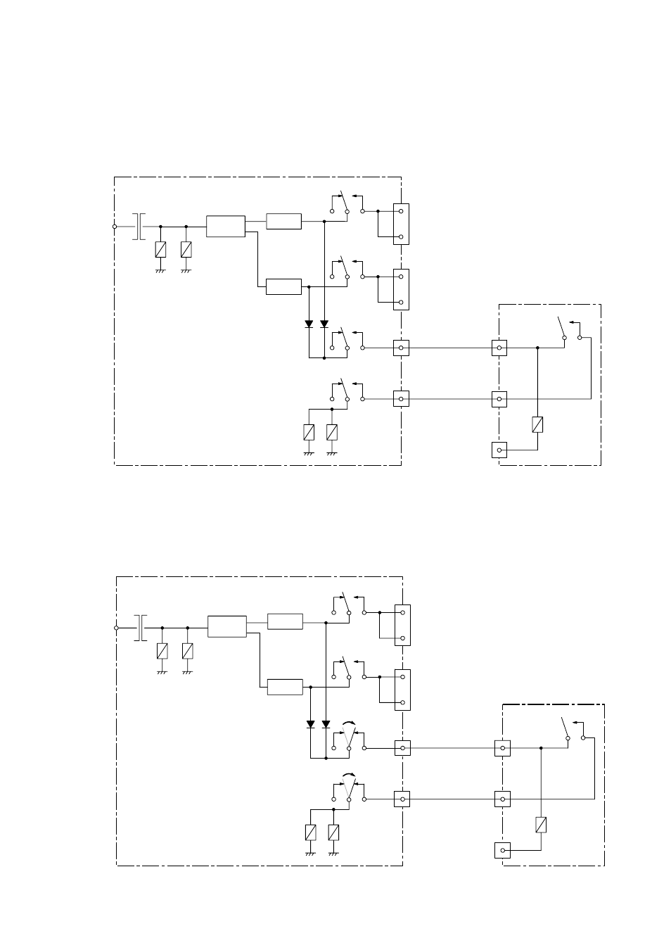
9.4.3. About the operation of the Emergency Power Supply Panel DS-029B
When the AC power is supplied and the Emergency Activation terminal is not shorted (standby
status)....
Current flows in coils D and E, and contact points d and e are as shown below. 24 VDC is not sent to
REMOTE (left) or outputs 1-4.
AC power
D
E
DS-029B
Charging
circuit
Battery 1
Battery 2
b
c
e
Output 1
Output 2
Output 3
Output 4
REMOTE (left)
REMOTE (right)
EMG ACTI
EMG DS ACTI
EMG DS CTRL
JP-0410
f
F
d
C
B
When the AC power is cut off (power failure)....
Because no current flows in coils D and E, contact points d and e switch as shown below. 24 VDC is output
from Batteries 1 and 2 via a diode. The 24 VDC power is not sent to outputs 1-4.
AC power
D
E
b
c
e
JP-0410
f
F
d
C
B
DS-029B
Charging
circuit
Battery 1
Battery 2
Output 1
Output 2
Output 3
Output 4
REMOTE (left)
REMOTE (right)
EMG ACTI
EMG DS ACTI
EMG DS CTRL